Procom SER-1P Manuel utilisateur

Technical Guide
SER-IP
Vin
Vo
I
OL
UV
OV
AF
MA
OPERATING INSTRUCTIONS
SER-1P

INDEX
• 1.0 Introduction
• 2.0 Salient Features
• 3.0 Display/Front Panel
• 4.0 Technical Specification
• 5.0 Relay Card Description:
• 6.0 Switches Description
• 7.0 LEDs Description
• 8.0 Parameter Mode
• 9.0 Setting Procedure: How to Enter in Parameter Mode
• 10.0 Setting Procedure: How to Restore Factory Settings
• 11.0 Setting Procedure: How to Enter in View Mode
• 12.0 Setting Procedure: How to Reset Password
• 13.0 Terminal Numbers
• 14.0 Connection Diagram
• 15.0 Dimensional Detail

0 1.0 Introduction
SER-1P is digital controller equipped with 3 row alphanumeric seven segment
display and 5 navigator keys simplifies configuration of controller.
0 2.0 Salient Features:
• 32 Bit RISC floating point microprocessor.
• Response time 60mSec.
• Fast Fourier Transformation to eliminate Harmonics & Surges/Sag.
• High performance & Accuracy.
• Simultaneous display of all measured quantity.
• Password protection for user programmable parameters.
Auto Mode
Selection
Switch
Output
Voltage
Increment
Switch
LED
Indication
Output
Voltage
Decrement
Switch
Reset
Switch
Manual
Mode
Selection
Switch
SER-IP
Vin
Vo
I
OL
UV
OV
AF
MA
0 3.0 Display/Front Panel:
• Fault Indication LEDs
• Manual /Auto mode LEDs
• Limit switches LEDs
• Manual/Auto selection switch.
• Output voltage Increment/Decrement switch.
• Reset switch.

0 4.0 Technical Specifications
Measurement Accuracy : Class 1(± 1% Of Full Scale)
Input Voltage : Vph, VN
Input Voltage Measured Range :10-350V AC (L-N)
Voltage Withstand : 800V L-L Max., 1000V for 1 Minute
Isolation Between Terminal & Body : 2kV
Input Current : Iph
Input Current Range : 0-6 A
Current Withstand : 10A Continuous, 50A for 1 Second
Input Frequency : 45 To 55 Hz
Auxiliary Supply : Ph-N(50-350V AC/DC)
Input/output Voltage Display : 1 Row 3 Digit
Input Current Display : 1 Row 3 Digit
Response Time : 60msec
Operating Temperature : -20°C to +70°C
Storage Temperature : -25°C to +80°C
Mounting : Panel Mount
Cut out Dimensions : 91mm X 91mm
0 5.0 Relay Card Description:
! For SER-1P four potential free output contacts are provided :
1. Phase Increase 2. Phase Decrease
3. Hooter 4. Trip.
! Relay Specifications
Contact Arrangement : 1 C/O
Contact Rating : 10A @ 230 VAC
6
Mechanical life expectancy : 10
5
Electrical life expectancy : 10
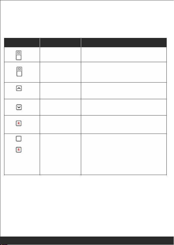
Auto Mode
By pressing the Auto switch for 3 sec ,
controller enters in Auto Mode.
Increment
By pressing the increment switch, the
output voltage limit can be increased.
Decrement
By pressing the decrement switch, the
output voltage limit can be decreased.
Reset
By pressing the Reset switch, hooter
and fault signals are reseted.
Programming
Mode
entry
Next
By pressing both switches (Auto &
Reset) the controller will enter in
programming mode.
After entering in programming mode
the Reset switch is used to select the
next parameter to be programmed.
A
Switch Symol
Switch Function
Description
Manual Mode
By pressing the Manual switch, for 3
sec controller enters in manual mode.
M
0 6.0 Switches Description:
PSR-3/PSR-1 has 6 switches provided on its front panel. The table below
describes the operation of these:
A
&

Low
Low LED glows continuously when low voltage
limit is reached.
High
High LED glows continuously when high voltage
limit is reached.
AF
AF LED glows continuously when auto
correction of set system output voltage is not
perceived.
OV
OV LED glows continuously when Over Voltage
is perceived.
UV
UV LED glows continuously when Under Voltage
is perceived.
OL
OL LED glows continuously when overload is
perceived.
0 7.0 LEDs Description
SER-1P has 8 LEDs provided on its front panel. The table below describes
the operation of these.
Nomenclature
Symbol
Description
Auto
Auto LED glows continuously when controller is
in Auto Mode.
Manual
Manual LED glows continuously when controller
is in Manual Mode.
M
A

Set Vol (Set output
voltage limit)
Set the desired output voltage.
230
200-550
Set Vol Hys
The desired output voltage
hysteresis.
10
1-20
CT Pri
The desired primary turns of CT
005
1-999
CT Sec
The desired secondary turns of CT
5
1-10
OV
The desired over voltage limit
280
200-300
OV HYS
The desired over voltage
hysteresis.
10
1-20
OV DLY
The desired over voltage fault
delay.
3
1-20
UV
The desired under voltage limit
200
100-300
UV HYS
The desired under voltage
hysteresis.
10
1-20
UV DLY
The desired under voltage fault
delay.
3
1-20
OL
The desired over load limit
005
1-999
OL DLY
The desired over load fault delay.
5
1-20
Hot
Hooter
120
1-999
Parameter
Name
on Display
Explanation of Parameter
Factory
Setting
Setting
Range
Ent PAS (Enter
password)
System settings are password
protected. Password is a three digit
number.
1
1-999
0 8. Parameter Mode
The following tables gives the detailed descriptions of parameter name/settings

0 9. Setting Procedure: How to Enter in Parameter Mode
• Press AUTO & RESET switches simultaneously. The controller shall
display, "Edt".
• To enter in edit parameter mode
Press Auto & Reset switch together
Edt appears on display.
Press "Reset" switch to move forward
Press Keys above
Together
Edt
&
Display will show PAS 1
Press INC or DEC switch to reach 1 which is the
default password. Once 1 is set Press "Reset "
switch to move forward
Ent PAS 1
Display will show PAS Ok
PAS OK
Press "Reset" switch to move forward
Display will show SET VOL 230
SET VOL 230
Press INC or DEC switch to select the desired Output
voltage. Press "Reset" switch to move forward
SVL HYS 1 Display will show SVL HYS 1
Press INC or DEC swtich to select the desired
Hyseteresis. Press "Reset" switch to move forward
A

OV DLY 3
UV 200
UV HYS 10
Display will show OV DLY 3
Press INC or DEC switch to select the desired
Over voltage fault delay. Press "Reset" switch to move
forward.
Display will show UV 200
Press INC or DEC switch to select the desired Under
voltage limit. Press ""Reset" switch to
move forward
Display will show UV HYS 10
Press INC or DEC switch to select the desired CT
Primary turns .Press "Reset" switch to move forward
Display will show CT SEC 005
CT SEC 005
Press INC or DEC switch to select the desired
CT Secondary turns. Press "Reset" switch to
move forward
OV 280 Display will show OV 280
Press INC or DEC switch to select the desired Over
Voltage limit. Press "Reset" switch to move forward
OV HYS 10 Display will show OV HYS 10
Display will show CT PRI 005
CT PRI 005
Press INC or DEC switch to select the desired Under
voltage Hysteresis.
Press "Reset" switch to move forward
Press INC or DEC switch to select the desired Over
voltage Hysteresis.
Press "Reset" switch to move forward

HOT 120 Display will show HOT 120
Press INC or DEC switch to select the desired Hooter
enable time.
Press "Reset" switch to move forward.
UV DLY 3
OL 005
OL DLY 5
Display will show UV DLY 3
Press INC or DEC switch to select the desired Under
voltage fault delay.
Press "Reset" switch to move forward
Display will show OL 005
Press INC or DEC switch to select the desired Over
Load limit. Press "Reset" switch to move forward
Display will show OL DLY 05
Press INC or DEC switch to select the desired Over
Load fault delay.
Press "Reset" switch to move forward.
Autres manuels Procom Contrôleurs


