Process Technology Tytan Manuel utilisateur

TYTANTM
Inline Water Heater
Instruction Manual
www.process-technology.com
7010 Lindsay Dr., Mentor, OH 44060 Phone: 440-974-1300 Fax: 440-974-9561 USA/CN: 800-621-1998

TABLE OF CONTENTS:
RELATED DOCUMENTS ...............................................................................................3
INTRODUCTION.............................................................................................................4
SYSTEM SPECIFICATIONS ..........................................................................................6
MODEL NUMBER.........................................................................................................10
MODEL NUMBER EXPLANATION.........................................................................................................11
FACILITY REQUIREMENTS ........................................................................................13
WATER PLUMBING REQUIREMENTS..................................................................................................14
ELECTRICAL REQUIREMENTS............................................................................................................14
INSTALLATION............................................................................................................15
INSPECTION AND UNCRATING ...........................................................................................................15
POSITIONING AND MOUNTING..................................................................................17
PLUMBING..............................................................................................................................................18
WIRING ...................................................................................................................................................20
RC1, RC2 COMMUNICATIONS (OPTIONAL)........................................................................................22
RC3 COMMUNICATIONS (OPTIONAL).................................................................................................23
RI REMOTE INTERFACE (OPTIONAL) .................................................................................................23
OPERATIONS ..............................................................................................................25
CONTROL PANEL..................................................................................................................................25
TEMPERATURE CONTROLLER E5CN.................................................................................................26
PARAMETER SETTINGS E5CN.........................................................................................................29
CHANGING SET POINT E5CN...........................................................................................................30
HIGH ALARM E5CN............................................................................................................................30
PID TUNING E5CN..............................................................................................................................31
TEMPERATURE CONTROLLER E5CK (RC OPTIONS).......................................................................32
PARAMETER SETTINGS E5CK.........................................................................................................35
CHANGING SET POINT E5CK...........................................................................................................36
HIGH ALARM E5CK............................................................................................................................37
PID TUNING E5CK..............................................................................................................................38
OVER TEMPERATURE CONTROLLER: FDC-L91................................................................................39
SYSTEM START UP...............................................................................................................................42
SYSTEM SHUT DOWN...........................................................................................................................42
MAINTENANCE............................................................................................................43
WARRANTY .................................................................................................................44
M-45-02 TYTAN Manual
Revision - Date: 01 – 11/16/07 2

RELATED DOCUMENTS:
The following documents are to be used in conjunction with this manual:
ANSI/NFPA70 – National Electric Code→, latest edition. To be used to determine
appropriate electrical service, wire sizing, routing and protection.
SEMI S2 – Semiconductor Equipment Safety Guidelines, latest edition. To be used in
conjunction with safe operation, access and decommissioning procedures.
OMRON E5CN INSTRUCTION MANUAL – To be used to access features of the E5CN
temperature controller. (Secure appropriate manual for any optional temperature
controller used in place of the E5CN).
OMRON E5CK INSTRUCTION MANUAL (for units with RC1, RC2 or RC3 option) –
To be used to access features of the E5CK temperature controller.
ANY – State or local building codes that would cover the electrical, mechanical, or
physical installation of electrical heating equipment.
National Electric Code→
NFPA 1999 Copyright
National Fire Protection Association
Quincy, Mass. 02269
M-45-02 TYTAN Manual
Revision - Date: 01 – 11/16/07 3

INTRODUCTION:
The following symbols and warning labels appear on the unit and in the instruction
manual. The table below provides an explanation of each one.
DESCRIPTION PICTORAL DESCRIPTION
DANGER indicates an imminently hazardous
situation which, if not avoided, will result in
death or serious injury. This signal word is to
be limited to the most extreme situations.
WARNING indicates a potentially hazardous
situation which, if not avoided, could result in
death or serious injury.
CAUTION indicates a potentially hazardous
situation which, if not avoided, may result in
minor or moderate injury. It may also be used
to alert against unsafe practices.
DANGER: HAZARDOUS VOLTAGE
ENCLOSED
Voltage or current hazard sufficient to cause
shock, burn or death. Disconnect and lock
out power before servicing.
WARNING: HAZARDOUS VOLTAGE
Contact may cause electric shock or burn.
This unit to be serviced by trained personnel
only.
CAUTION: HOT SURFACE. DO NOT
TOUCH
Heater column may be hot. Allow unit to cool
before servicing.
PROTECTIVE EARTH (GROUND)
Table 1: TYTAN Warning Labels
M-45-02 TYTAN Manual
Revision - Date: 01 – 11/16/07 4

INTRODUCTION (Continued):
The TYTAN water heater is designed for inline heating of de-ionized (DI) water, city
water, reverse-osmosis (RO) water, and filtered seawater. It can perform both as a
recirculating heater or a single-pass heater.
TEMPERATURE PERFORMANCE: The TYTAN water heater is designed to provide a
specified temperature increase at a given flow rate. Table 2 shows the maximum
temperature increase (∆T) that can be achieved for continuous flow conditions at the
specific heater power ratings varying from 24 kW to 144 kW (Higher wattage systems
available upon request). The temperature control system provided with the heater will
modulate the power to the heating columns in order to maintain your specific outlet
temperature setting.
Heater Power (Kilowatts)
Flow Rate 12 18 24 36 48 72 96 120 144
GPM Maximum Theoretical Temperature Rise (°F)
1 80.8 121.2 - - - - - - -
2 40.4 60.6 80.8 121.2 - - - - -
4 20.2 30.3 40.4 60.6 80.8 121.1 - - -
6 13.5 20.2 26.9 40.4 53.8 80.8 107.7 134.6 -
8 10.1 15.1 20.2 30.3 40.4 60.6 80.8 101.0 121.2
10 8.0 12.1 16.1 24.2 32.3 48.4 64.6 80.8 96.9
12 6.7 10.1 13.4 20.2 26.9 40.4 53.8 67.3 80.8
14 5.7 8.6 11.5 17.3 23.0 34.6 46.1 57.7 69.2
16 5.0 7.5 10.1 15.1 20.2 30.3 40.4 50.5 60.6
18 4.5 6.7 8.9 13.4 17.9 26.9 35.9 44.8 53.8
20 4.0 6.0 8.0 12.1 16.1 24.2 32.3 40.4 48.4
22 3.6 5.5 7.3 11.0 14.6 22.0 29.3 36.7 44.0
24 3.3 5.0 6.7 10.1 13.4 20.2 26.9 33.6 40.4
Table 2: Maximum Temperature Rise
SAFETY DEVICES: The TYTAN water heaters include a comprehensive system of
safety controls and devices to insure safe and long-lasting operation. The list of
safeties is included in Table 3: system specifications provided on the following page.
M-45-02 TYTAN Manual
Revision - Date: 01 – 11/16/07 5

SYSTEM SPECIFICATIONS:
Product TYTAN inline titanium water heater
Standards UL, cUL standard
CE, SEMI S3 optional (-SC)
Available Wattage Range 12kW – 144kW
Refer to model number label for the wattage of any specific unit
Available Voltages 208V – 600V, 50/60Hz, 3 phase standard
(Some voltages available in single phase or with special construction,
consult factory for details)
Cabinet dimensions: Width Depth Height Weight
12kW – 48kW 28.5-in (75 cm) 13.5-in (34 cm) 36-in (91 cm) 145 lbs. (66 kg)
72kW 37.5-in (95 cm) 13.5-in (34 cm) 36-in (91 cm) 230 lbs. (104 kg)
96kW – 144kW 28-in (71 cm) 17-in (43 cm) 63-in (160 cm) 300 lbs. (136 kg)
Wetted surfaces:
Heating elements CP2 titanium standard, (316SS optional [-S option])
Columns and plumbing CP2 titanium standard, (316SS optional [-S option])
PRV Valve PVDF
Operating temperatures:
Process inlet
Process outlet Up to 194°F (90°C), depending upon operating conditions
Temperature accuracy +/- 1°F, depending upon operating conditions
Ambient air temperature 86°F (30°C) maximum
Water pressure range Minimum 10 psi (69 kPa, 0.69 bar)
Maximum 100 psi (690 kPa, 6.9 bar)
Minimum water flow rate:
12kW - 24kW 0.5 gpm (2 lpm)
36kW – 48kW 1.0 gpm (4 lpm)
72 kW 1.5 gpm (6 lpm)
96kW 2.0 gpm (8 lpm)
120kW 2.5 gpm (10 lpm)
144kW 3.0 gpm (12 lpm)
Standard Safety Devices: EMO Pushbutton
Pressure Relief Valve (PRV), connected to inlet manifold
Electrically grounded heating chamber construction
Ground Fault Protection (GFP)
Safety Limit Control (SLC)
Bimetallic heater over temperature sensor(s)
Heater outlet overtemperature alarm
Solid state relay (SSR) overheat bimetallic sensor
Sensor failure detection
Control circuit fuse protection
Table 3: TYTAN Specifications
M-45-02 TYTAN Manual
Revision - Date: 01 – 11/16/07 6

SYSTEM SPECIFICATIONS (Continued):
Figure 1: Dimensional Drawing, 12kW – 48kW Units
M-45-02 TYTAN Manual
Revision - Date: 01 – 11/16/07 7

SYSTEM SPECIFICATIONS (Continued):
Figure 2: Dimensional Drawing, 72kW Unit
M-45-02 TYTAN Manual
Revision - Date: 01 – 11/16/07 8
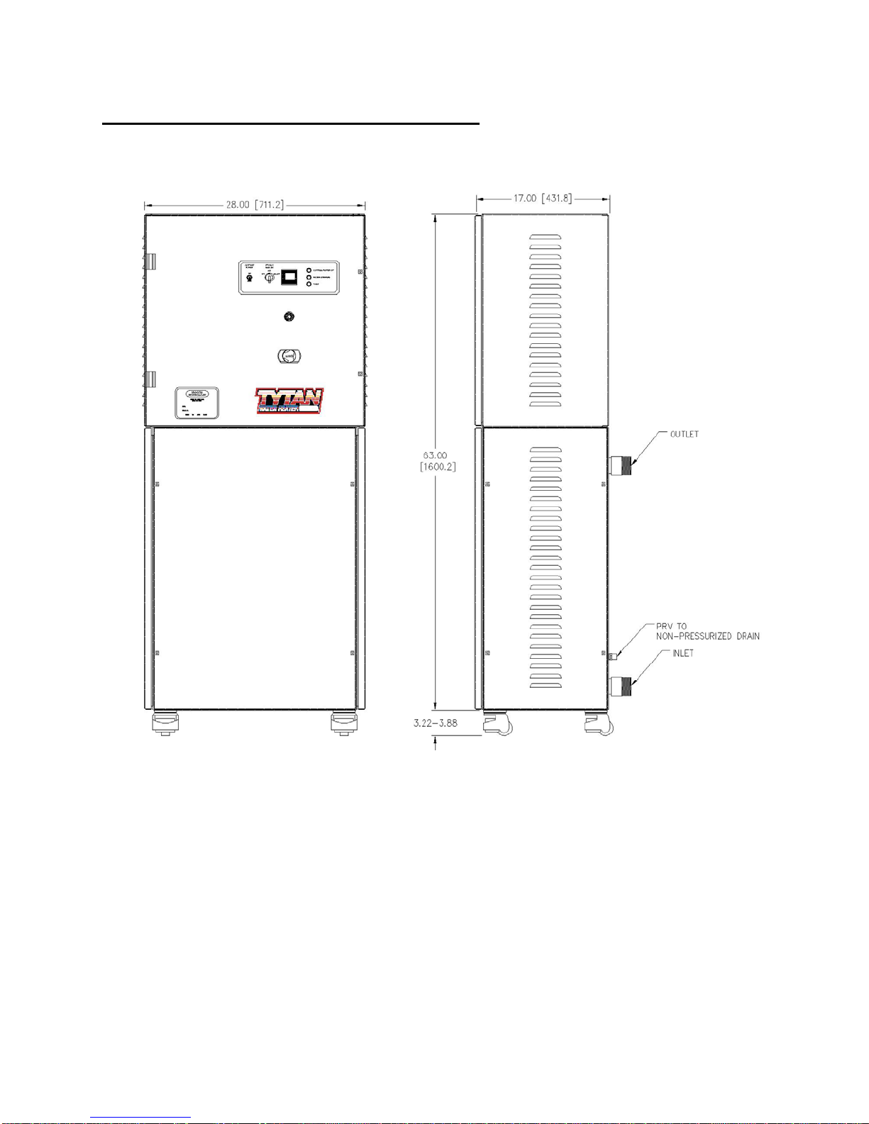
SYSTEM SPECIFICATIONS (Continued):
Figure 3: Dimensional Drawing, 96kW – 144kW Units
M-45-02 TYTAN Manual
Revision - Date: 01 – 11/16/07 9

MODEL NUMBER:
Process Technology model numbers are designed to offer some description of the
heater construction, including features and options. The model number can be found on
the model/serial number label located on the front of the unit, near the bottom (see
figures 1-3).
Figure 4: Model/Serial Number Label
M-45-02 TYTAN Manual
Revision - Date: 01 – 11/16/07 10
Table des matières
Autres manuels Process Technology Chauffe-eau


Manuels Chauffe-eau populaires d'autres marques

Kenmore
Kenmore 153.582400 Manuel utilisateur

Applimo
Applimo Edel AIR Manuel utilisateur

STIEBEL ELTRON
STIEBEL ELTRON Eltronom SHU 5 S Manuel utilisateur

clage
clage E-Mini Series Manuel utilisateur

Toyotomi
Toyotomi Oil Miser OM-180 Manuel utilisateur

Bradford White
Bradford White EF Series Manuel utilisateur


 Guide de dépannage")


