Pro-tec 6000/LOOP/REPEATER Manuel utilisateur


RDM0012 Issue 1 AA Page 2 of 35 © Protec Fire Detection PLC 2017
Document Revision Details
Issue
Modification Details
Author
Date
0
Document creation
AA
07/02/2017
1
Added default access codes, updated the programming
guide
AA
05/10/2017
Notice
This manual may be revised as a result of enhancements to the device software or hardware. Check
for revisions to this manual, and download them, from the website. www.protec.co.uk

RDM0012 Issue 1 AA Page 3 of 35 © Protec Fire Detection PLC 2017
Table of Contents
TABLE OF CONTENTS .................................................................................................................................3
1.0 INTRODUCTION...............................................................................................................................4
2.0 GLOSSARY OF TERMS.......................................................................................................................4
3.0 PROGRAMMING GUIDE...................................................................................................................5
3.1 Programmable Items .......................................................................................................................... 5
3.2 PC / Laptop Requirements ................................................................................................................. 5
3.3 Items Required for Device Programming ........................................................................................ 5
3.4 Protec Stand Alone Repeater Programmer Software Installation ............................................... 6
3.5 Connecting the Device to the PC ..................................................................................................... 11
3.6 Updating the Device Firmware ........................................................................................................ 12
3.7 Programming Device Custom Data and Logos ............................................................................. 14
4.0 INSTALLATION GUIDE...................................................................................................................18
4.1 Packaging Contents........................................................................................................................... 18
4.2 Front Panel Removal ......................................................................................................................... 19
4.3 Mounting............................................................................................................................................. 20
4.4 Insulation and Continuity Testing of Cabling ................................................................................ 21
4.5 Connecting the Front Panel.............................................................................................................. 21
4.6 Fitting the Front Panel....................................................................................................................... 22
5.0 USER RESPONSIBILITIES ...............................................................................................................23
5.1Requirements of the Premises Management Named Person .................................................... 23
6.0 ROUTINE TESTING OF THE DEVICE...............................................................................................24
6.1 Daily Inspection.................................................................................................................................. 24
6.2 Weekly Test ......................................................................................................................................... 24
7.0 USER GUIDE....................................................................................................................................25
7.1 Controls ............................................................................................................................................... 25
7.2 LED Indicators .................................................................................................................................... 25
7.3 Push Buttons ...................................................................................................................................... 26
7.4 Access Levels ...................................................................................................................................... 26
7.5 Browsing System Events................................................................................................................... 27
7.6 Help Menu........................................................................................................................................... 28
7.7 Access Level 1 Controls Menu.......................................................................................................... 29
8.0 ENGINEER MENU GUIDE ...............................................................................................................30
8.1 Login to Access Level 3...................................................................................................................... 30
8.2 Change the GUI Language ............................................................................................................... 31
8.3 Event Category Enablement............................................................................................................. 32
8.4 Default Access Codes ........................................................................................................................ 33
9.0 APPENDIX 1 - INSTALLATION TEMPLATE ....................................................................................34

RDM0012 Issue 1 AA Page 4 of 35 © Protec Fire Detection PLC 2017
1.0 Introduction
The 6000/LOOP/REPEATER is a low power Fire Alarm Repeat Display, designed to complement Protec’s
range of control panels. Events from the panel are displayed on the device’s LCD, providing system
indication to any loop connected location on a site. The device only requires a loop connection to
provide both power and data, no network cabling, or external power supply is required.
2.0 Glossary of Terms
GUI
Graphical User Interface, graphics displayed on the screen of the device for user interaction.
Device
Refers to the 6000/LOOP/REPEATER.
Protec
Refers to Protec Fire Detection PLC.
There are no user serviceable parts inside the 6000/LOOP/REPEATER.
This equipment has been manufactured in conformance with the requirements of all
applicable EU council directives and regulations.
Electrical or electronic devices that are no longer serviceable must be collected separately
and sent for environmentally compatible recycling (in accordance with the European
Waste Electrical and Electronic Equipment Directive). To dispose of old electrical or
electronic devices, you should use the return and collection systems put in place in the
country concerned.
The policy of Protec Fire Detection PLC is one of continuous improvement. As such we reserve the
right to make changes to product specifications at any time and without prior notice.

RDM0012 Issue 1 AA Page 5 of 35 © Protec Fire Detection PLC 2017
3.0 Programming Guide
The 6000/LOOP/REPEATER is programmed with a default configuration out of the box. If a custom
configuration is required, this can be programmed through the device’s USB port, using the Protec
Stand Alone Repeater Programmer windows software. The programming software also enables
updates of the device’s firmware if required. Note that some basic settings can also be configured on
the device itself through the engineer menu.
3.1 Programmable Items
The following items can be downloaded through the Protec Stand Alone Repeater Programmer.
Item
Programming Software
Configure on Device
Bootloader Update
✖
✖
Firmware Update
✔
✖
Responsible Person and Installer Text
✔
✖
Level 2 & 3 Access Codes
✔
✔
Device GUI Language
✔
✔
Custom Site and Installer Logos
✔
✖
Device Home Screen Selection
✔
✔
Event Category Filtering
✔
✔
3.2 PC / Laptop Requirements
The PC used to connect to the device must conform to the following minimum specification.
1 GHz processor (Intel ATOM processors are not recommended)
1 GB RAM (2GB for 64bit)
1 GB available hard disk space
One free USB 2.0 communications port (for connection to the device)
Windows® 7 or Windows® 10 (32bit or 64bit)
Windows® XP SP2 or SP3 (not recommended)
3.3 Items Required for Device Programming
Windows® PC of the aforementioned specification
Protec Stand Alone Repeater Programmer software
USB Type A Male to Micro-USB Type B Male cable (USB 2.0, max length 2m)

RDM0012 Issue 1 AA Page 6 of 35 © Protec Fire Detection PLC 2017
3.4 Protec Stand Alone Repeater Programmer Software Installation
The software executable can be obtained by contacting Protec Fire Detection, or visiting the Protec
website.
3.4.1 Opening the Executable Installer
Once the software has been obtained, double-click the executable file to open it.
Press ‘Next >‘ on the resulting window to start the installation.
3.4.2 Licence Agreement
Carefully read the licence agreement before continuing.
When happy with the agreement tick ‘I accept the agreement’then press ‘Next >‘to continue.
The installation cannot be completed without accepting this agreement.

RDM0012 Issue 1 AA Page 7 of 35 © Protec Fire Detection PLC 2017
3.4.3 Start Menu Folder
It is possible to change the default Start Menu folder if required.
It is recommended to keep this as the default value set by the installer. Press ‘Next >‘to continue.
3.4.4 Additional Tasks
It is possible to create a desktop icon for the Stand Alone Repeater Programmer.
It is recommended to create a desktop icon.
Tick ‘Create a desktop icon’then press ‘Next >‘to continue (this will begin the software installation).

RDM0012 Issue 1 AA Page 8 of 35 © Protec Fire Detection PLC 2017
3.4.5 Installation
The Stand Alone Repeater Programmer will be installed on the system.
Once the installation is completed, the Stand Alone Repeater Programmer can be launched.
RDM0012 Issue 1 AA Page 9 of 35 © Protec Fire Detection PLC 2017
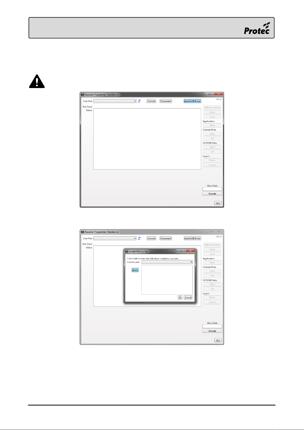
3.4.6 USB Driver Installation
The Stand Alone Repeater Programmer should now be installed and open. It is now required to install
the USB driver needed to communicate with the 6000/LOOP/REPEATER.
Ensure the device is not connected to the PC at this point.
Press ‘Install USB Driver’in order to open the installation window.
Press ‘Install’on the new window in order to start the driver installation.
Follow any on-screen prompts and accept any Windows User Account Control messages.

RDM0012 Issue 1 AA Page 10 of 35 © Protec Fire Detection PLC 2017
The USB driver should now be installed, and the device can now be connected to the PC. The USB
driver installation window can be closed.
Table des matières
Autres manuels Pro-tec Alarme incendie


