
PreView WS6010 Manuel utilisateur

COLLISION ALERT SYSTEMS APS-SUPPLY.COM
www.aps-supply.com
APS USA
610 Gateway Center Way, Suites J & K
San Diego, CA 92102 USA
P: 1 619 263 4164
F: 1 619 263 6814
APS Australia
U48 / 9 Vision Street,
Wangara WA 6065 Australia
P: 61 (8) 9302 2369
F: 61 (8) 6305 0047
APS: Singapore
Colombia
Chile
Perú
Brasil
WorkSight® PreView®
WS6010/WS6015/WS6020
Operating Manual

COLLISION ALERT SYSTEMS APS-SUPPLY.COM
www.aps-supply.com
APS USA
610 Gateway Center Way, Suites J & K
San Diego, CA 92102 USA
P: 1 619 263 4164
F: 1 619 263 6814
APS Australia
U48 / 9 Vision Street,
Wangara WA 6065 Australia
P: 61 (8) 9302 2369
F: 61 (8) 6305 0047
APS: Singapore
Colombia
Chile
Perú
Brasil
FCC STATEMENT
This device complies with Part 15 of the FCC Rules. Operation is subject to the
following two conditions: (1) this device may not cause harmful interference, and
(2) this device must accept any interference received, including interference that
may cause undesired operation.
Warning: Changes or modications to this unit not expressly approved by the
party responsible for compliance could void the user’s authority to operate the
equipment.
NOTE: This equipment has been tested and found to comply with the limits of
a Class B digital device, pursuant to Part 15 of the FCC Rules. These limits
are designed to provide reasonable protection against harmful interference in a
residential installation. This equipment generates, uses, and can radiate radio
frequency energy and, if not installed and used in accordance with the instructions,
may cause harmful interference to radio communications. However, there is
no guarantee that interference will not occur in a particular installation. If this
equipment does cause harmful interference to radio or television reception, which
can be determined by turning the equipment off and on, the user is encouraged
to try and correct the interference.
PATENTS
Patented under one or more of the following U.S. Patents:
5345471, 5523760, 5457394, 5465094, 5512834, 5521600, 5682164, 5630216,
5510800, 5661490, 5609059, 5774091, 5757320, 5581256, 5832772, 5519400,
5767953, 5767627, 5589838, 5563605, 5661385, 5517198, 5610611, 5883591,
5805110, 5754144, 7088284, and 7215278.
Other patents have been applied for.
TRADEMARKS
The names of actual companies and products mentioned herein may be the
trademarks of their respective owners. Any rights not expressly granted herein
are reserved.

COLLISION ALERT SYSTEMS APS-SUPPLY.COM
www.aps-supply.com
APS USA
610 Gateway Center Way, Suites J & K
San Diego, CA 92102 USA
P: 1 619 263 4164
F: 1 619 263 6814
APS Australia
U48 / 9 Vision Street,
Wangara WA 6065 Australia
P: 61 (8) 9302 2369
F: 61 (8) 6305 0047
APS: Singapore
Colombia
Chile
Perú
Brasil
CONTENTS
Product Description .............................................................................................
Sensor/Antenna Description ................................................................................
Operator Display Description..................................................................
Object Detection Capability ....................................................................
Installation Instructions ........................................................................................
Before You Start ......................................................................................
Sensor/Antenna Location .......................................................................
Sensor/Antenna Mounting ......................................................................
Sensor Power Connection ......................................................................
Aux. Output Electrical Connection ..........................................................
Display Unit Installation ..........................................................................
Cable Installation ....................................................................................
Initial System Power Up and Test ...........................................................
PreView® Daily Maintenance ..............................................................................
Testing and Maintenance ........................................................................
Troubleshooting ..................................................................................................
Specications .....................................................................................................
Warranty Information .........................................................................................
PreView® Conguration Options: ......................................................................
1
2
2
4
6
6
6
6
7
7
7
7
8
9
9
11
12
13
14

COLLISION ALERT SYSTEMS APS-SUPPLY.COM
www.aps-supply.com
APS USA
610 Gateway Center Way, Suites J & K
San Diego, CA 92102 USA
P: 1 619 263 4164
F: 1 619 263 6814
APS Australia
U48 / 9 Vision Street,
Wangara WA 6065 Australia
P: 61 (8) 9302 2369
F: 61 (8) 6305 0047
APS: Singapore
Colombia
Chile
Perú
Brasil
Product Description
The WorkSight® PreView® is a solid-state, pulsed radar object detection system
designed to alert vehicle operators to the presence of obstacles. The system
detects both moving and stationary objects in a pre-dened coverage area and
reports the distance of the closest object via visual range indicators and an
audible signal to the vehicle operator.
The WorkSight PreView models consist of three major components: an
environmentally sealed sensor, an operator display mounted in the cab of the
vehicle, and an interconnect cable. The WorkSight PreView system does not
require cleaning and is not affected by harsh weather conditions, including
temperature extremes, rain, sleet, snow, or fog. The WorkSight PreView Model
WS6020 has a twenty foot (six meters) detection range, the WS6015 has a 15
foot detection range (4.5 meters), and the WS6010 has a 10 foot detection range
(3 meters).
Figure 1. WorkSight® PreView®

COLLISION ALERT SYSTEMS APS-SUPPLY.COM
www.aps-supply.com
APS USA
610 Gateway Center Way, Suites J & K
San Diego, CA 92102 USA
P: 1 619 263 4164
F: 1 619 263 6814
APS Australia
U48 / 9 Vision Street,
Wangara WA 6065 Australia
P: 61 (8) 9302 2369
F: 61 (8) 6305 0047
APS: Singapore
Colombia
Chile
Perú
Brasil
Sensor / Antenna Description
The antenna assembly transmits and receives low power 5.8GHz radar signals.
It then processes the returned signals to determine if an object has reected any
energy back to the sensor and reports this to the operator display. The sensor
is designed to process and report detections within ½ of a second allowing the
vehicle operator to quickly respond to any object within the detection zone. All
connections to a vehicle are accomplished at the sensor. Power is typically
obtained from the vehicle reverse lights. The connection to the display unit is
through a watertight connector eliminating any potential problems with pin
corrosion. Power to the operator display is provided through the sensor interface
to the display.
The WorkSight PreView sensor has a continuous Built In Self Test which noties
the operator of sensor failure within a fraction of a second.
Operator Display Description
The operator display provides the vehicle operator with a visual indication of a
detected object. The display unit also contains a buzzer* to provide an audible
alert that will increase in rate as an object becomes closer, providing the operator
with another cue that an object is being detected.
The operator display continuously monitors communication from the WorkSight
PreView sensor and in the event of a system failure or malfunction, will notify the
operator with a fault indication.
A switch* is provided on the front panel of the display allowing the vehicle operator
the ability to adjust the buzzer volume to three different levels or to provide an
alarm acknowledge and silence the buzzer.
*OC models do not include the buzzer or switch. Switch functionality is disabled
on NVC models.

COLLISION ALERT SYSTEMS APS-SUPPLY.COM
www.aps-supply.com
APS USA
610 Gateway Center Way, Suites J & K
San Diego, CA 92102 USA
P: 1 619 263 4164
F: 1 619 263 6814
APS Australia
U48 / 9 Vision Street,
Wangara WA 6065 Australia
P: 61 (8) 9302 2369
F: 61 (8) 6305 0047
APS: Singapore
Colombia
Chile
Perú
Brasil
Figure 2. Operator Display
Item Description
Status LED
Illuminates green continuously after power is applied to the system.
The status will change from green to red if a system malfunction
occurs.
Range Indications
Illuminate to give operator a relative distance measurement to the
closest detected object. LED’s operate from the left to right, with a
closer object resulting in more LED’s illuminated.
Display Buzzer* Sounds audible tones to alert operator of obstacles. The speaker
pulse rate will increase as the vehicle gets closer to an object.
Volume Control/Ack Switch*
This momentary push button switch allows three different buzzer
volume levels to be selected. It can also be congured as an
acknowledge switch to silence the buzzer using the Service Tool.
Table 1. Operator Display Description
*OC models do not include the buzzer or switch. Switch functionality is disabled
on NVC models.

COLLISION ALERT SYSTEMS APS-SUPPLY.COM
www.aps-supply.com
APS USA
610 Gateway Center Way, Suites J & K
San Diego, CA 92102 USA
P: 1 619 263 4164
F: 1 619 263 6814
APS Australia
U48 / 9 Vision Street,
Wangara WA 6065 Australia
P: 61 (8) 9302 2369
F: 61 (8) 6305 0047
APS: Singapore
Colombia
Chile
Perú
Brasil
Object Detection Capability
The PreView® system is designed to supplement other safety practices and/or
devices, and is not to be the sole method of collision avoidance. The machine
operator is always the rst line of defense when safely operating a vehicle.
The WorkSight PreView system can detect most objects within the detection zone.
However, there are some instances where objects can go undetected. Obstacle
size, shape, relative location, and composition are all factors determining if, when
and where an object is detected. The PreView system operates by transmitting
a pulse of very low power electromagnetic energy. Any energy that strikes an
object reects a certain amount of this energy back to the PreView sensor. If the
returned energy is of sufcient magnitude, it is used to indicate object presence
and determine the object’s distance. While the PreView system can resolve
multiple objects, only the object closest to the vehicle is reported to the operator
display since it represents the most signicant collision threat.
The amount of energy returned is based on a few factors:
Size – a larger object usually reects more energy than a smaller object.
Composition – a metal object typically reects more energy than a non-metallic
object. A metallic object at the edge of the maximum detection zone might be
detected, whereas a wood object may not.
Scattering – a solid object reects more energy that a non-solid object such as
tree branches, gravel, bushes, etc.
Shape – complex shapes cause energy to be returned in a very non-uniform way.
Very small variations or movement can change detection status.
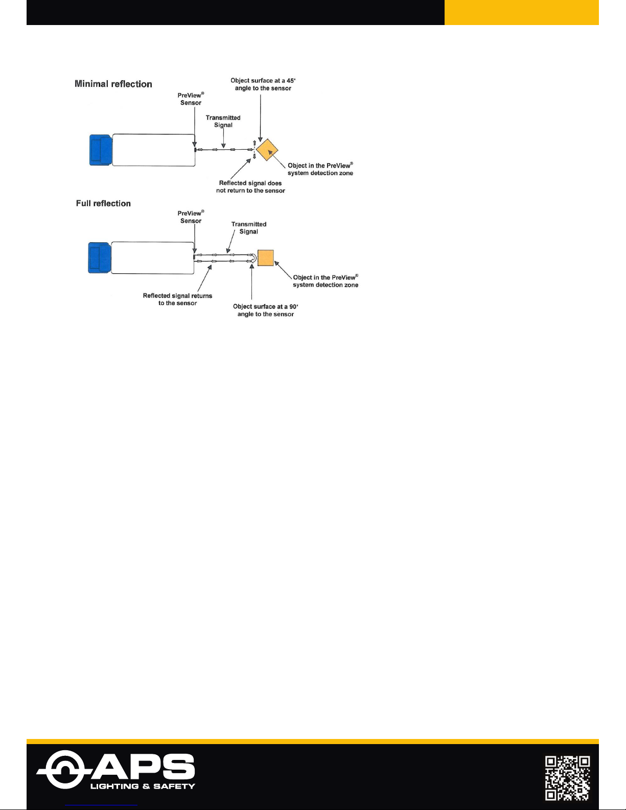
Angle – an object at side perpendicular to the sensor will reect more energy
than an object at an angle. See below for an example of how angle can affect
return energy.
COLLISION ALERT SYSTEMS APS-SUPPLY.COM
www.aps-supply.com
APS USA
610 Gateway Center Way, Suites J & K
San Diego, CA 92102 USA
P: 1 619 263 4164
F: 1 619 263 6814
APS Australia
U48 / 9 Vision Street,
Wangara WA 6065 Australia
P: 61 (8) 9302 2369
F: 61 (8) 6305 0047
APS: Singapore
Colombia
Chile
Perú
Brasil
Figure 3. Object Reection

COLLISION ALERT SYSTEMS APS-SUPPLY.COM
www.aps-supply.com
APS USA
610 Gateway Center Way, Suites J & K
San Diego, CA 92102 USA
P: 1 619 263 4164
F: 1 619 263 6814
APS Australia
U48 / 9 Vision Street,
Wangara WA 6065 Australia
P: 61 (8) 9302 2369
F: 61 (8) 6305 0047
APS: Singapore
Colombia
Chile
Perú
Brasil
Installation Instructions
Before you Start
Prior to installing the WorkSight PreView Object Detection System take time
to familiarize yourself with the installation instructions, theory of operation, and
system components. Check the contents of the shipping package and verify the
following items are included:
Antenna Sensor (1)
Display Unit (1)
Interconnect Cable (1)
User Manual/Operating Instructions and drill template
Sensor Stainless Steel Mounting Hardware
1-1/4” x 10-24 Bolts, Hex Locking Nuts, and Washers (4)
Display Hardware Kit
Mounting Bracket (1)
Mounting Hardware (1)
Sensor / Antenna Location
The WorkSight PreView sensor mounting location is integral to proper system
operation. Ideally the sensor should be mounted on the rear center of the vehicle
at roughly 36” (1M) +/- 12” (0.3M) above the ground. The sensor face should be
perpendicular to the ground with the “PreView” graphic in normal position. Select
a location that will provide some protection from impact and debris while allowing
an unobstructed view of the target hazard area.
Important!
Before the WorkSight PreView system is permanently installed to the vehicle,
verify that the selected sensor mounting location provides a clear detection zone.
Temporarily attach the sensor in the proposed mounting location, apply power to
the system, and verify that nothing is being detected.
Sensor / Antenna Mounting
1. Select the appropriate sensor mounting location.
2. The correct mounting conguration is with the sensor’s text in normal reading
position.
3. Using the drill template, scribe position marks through the holes. Drill 1/4”
(6mm) holes centered at the marks.
4. A 1-1/2” diameter clearance hole is required for the sensor connector and
mating cable connector.
5. Secure the sensor to the vehicle with the four supplied 10-24 UNC button
head screws, washers and nuts or equivalent. Apply a maximum torque of 22
inch pounds when securing the sensor.

COLLISION ALERT SYSTEMS APS-SUPPLY.COM
www.aps-supply.com
APS USA
610 Gateway Center Way, Suites J & K
San Diego, CA 92102 USA
P: 1 619 263 4164
F: 1 619 263 6814
APS Australia
U48 / 9 Vision Street,
Wangara WA 6065 Australia
P: 61 (8) 9302 2369
F: 61 (8) 6305 0047
APS: Singapore
Colombia
Chile
Perú
Brasil
Aux. Output Electrical Connection
This sensor provides an auxiliary output that can be used to activate an external
backup alarm or other device (white wire). Depending on the system ordered,
the cable provided may or may not have provisions to access this output.
The aux. output is activated whenever an object is detected. The output is switched
from a high impedance state to ground when active and is protected against an
over current condition. The maximum operating current is approximately 1 amp,
this includes any inrush current. For alarms or other devices that meet the 1 amp
maximum current, connect the aux. output wire on the interconnect harness to
the ground wire of the alarm or device. For alarms or devices that exceed the 1
amp current limit an intermediary relay must be used.
Display Unit Installation
The display unit should be mounted where the vehicle operator can easily view
it while backing. The ideal location for this is on the dash positioned by either
windshield pillar. This will allow the operator view of the display while also looking
out one of the side mirrors.
The WorkSight PreView display unit comes equipped with a mounting bracket
and hardware. If desired, the display unit can be mounted to the display bracket
with the supplied hardware. This bracket can then be mounted in the vehicle cab
as desired.
Cable Installation
The standard interconnect cable between the sensor and display is 30 feet (9.1M)
in length. If the distance between the sensor and display is greater than 30 feet,
contact Preco for a longer interconnect cable.
Sensor Power Connection
Locate the vehicle’s reverse light power wire and connect to the red wire on
the sensor harness using 18AWG wire minimum. Connect the black wire of the
sensor harness to vehicle ground.
Figure 4. Sensor Power Connection
Ce manuel convient aux modèles suivants
2
Table des matières
Manuels Système de sécurité populaires d'autres marques


EDM
EDM Solution 6+6 Wireless-AE Manuel utilisateur

Highway Safety Group
Highway Safety Group EA401 Manuel utilisateur

Siren
Siren LED GSM Manuel utilisateur

Detection Systems
Detection Systems 7090i Instructions de montage

Se-Kure Controls
Se-Kure Controls MicroMini SK-4841 Manuel utilisateur

Siemens
Siemens FDM273 Manuel utilisateur