PPSTinc 12.5-135/400 Manuel utilisateur

Induction Power Supplies
12.5KW; 135 – 400 KHz
LCD Display
(Integral Heat Station)
User’s Guide
Model 12.5-135/400
05/08
Rev D

1. Specifications and features...................................................................................... 3
2. Getting started........................................................................................................... 6
3. Connections .............................................................................................................. 8
4. Front panel description and operation.................................................................. 10
5. Programming and Status monitor ......................................................................... 16
6. Load station tuning. ................................................................................................ 22
7. APPENDIX A: USER INTERFACE........................................................................... 25
8. Layout.………………………………………………………………………………………27
9. Finding dew point…………………………………………………………………………28
2

1. Specifications and features
1.1. Output
Maximum Power 12.5kW1
Maximum Apparent Power 25kVA @ 240V input
Minimum Power Factor 0.5 @ 480V input
Duty Cycle 100%
Maximum Voltage 500V 2
Power Transformers (6) 2 :1
Frequency Range 135kHz to 400kHz
Maximum response time 0.1s3
Minimum Allowed OFF-Time 0.5s
1.2. Input
AC line-to-line voltage 240V 10%, 3
, 50 to 60Hz
AC line current 35A @ 240V
AC power 14.5kVA
1.3. Physical
Dimensions: Depth
Width
Height
16in (41cm)
20in (51cm)
43.75in (111cm)
Weight 275lb (125kg) approximately
1 Inverter output power i.e. includes power losses in heat station.
2 Mainly limited by the rating of resonant capacitors. Consult manufacturer for operating
at output voltages above 500V rms.
3 When using the adjustable start-frequency feature.
3

1.4. Front panel controls and indicators
LED Indicators
Yellow indicator for limit.
Red indicators for fault and trip.
Red indicator for fault.
Yellow and Green indicators for heat
on and off.
Numeric Displays Run time read-outs for:
Job and Step for Programmed mode
Elapsed time for heat period
power meter (0-100%)
LCD Display Working mode and Messages for fault,
trip and limit
Run time read-outs for:
Power demand, operating frequency,
capacitor voltage and inverter current
Controls – Switch and knob Push button switch for Heat ON/OFF.
Single turn knob for power level.
(Manual mode)
Pushbutton to reset trips.
Emergency stop button.
Program keys 21 keys for Program and monitoring
command
4

1.5. Internal heat station
Resonant capacitors Mounting space provided for sixteen
capacitors. Eight 210nF, 500V or 8
200nF, 700V capacitors supplied.
330nf available
Series Parallel Capacitor Rail Kit available (optional)
Series inductor Adjustable for load matching
1.6. Protection
Power Limited to 12.5kW in any feedback
configuration
Inverter output current Limited to 250A peak. Short circuit
protected.
Resonant capacitor voltage Limited to 500V rms
Line current 50A Circuit breaker
DC link current 80A Semiconductor fuse
Temperature and cooling water Temperature switch on inlet water.
Differential pressure switch between
water inlet and outlet.
Safety Interlocks Emergency stop button or door switch
opens the main circuit breaker.
1.7. Load
Quality factor of load Will operate with any load Q (including
resistive loads), provided that the
output frequency and voltage is within
the specifications.
Connection Selectable between left and right.
Custom output connection provided.
1.8. Cooling water
Maximum pressure 100PSI (690kPa)
Minimum differential pressure 30PSI (207kPa)
Minimum water flow 2GPM (0.126l/s)
Maximum inlet water temperature 110F (43.3C)
Minimum inlet water temperature Approx. 90º F (32ºC)**
Minimum water resistivity 590.in (1500.cm)
Supply hose location Selectable between left or right
** must be set above dew point (see page 29)
5

2. Getting started
2.1. Safety Warnings
HIGH FREQUECY RADIATION can interfere with radio navagation, safety
services, computers and communication equiptment.
Have only qualified person familiar with electronic equiptment perform this
installation.
The user is responsible for having a qualified electrician promptly correct any
interference problem resulting from the installation.
Any modifications performed on this power supply may void warranty.
Contact manufactor for approval before any modifications are performed.
Have the installation regularly checked and maintained.
Keep high-frequency source door and panels tightly shut.
1. Read this operation manual completely before using the power supply.
2. Induction heating can be dangerous. Obey all warnings on unit and in
manual.
3. Do not touch live electrical parts. In operation, this means the output
connectors, the work coil, the work piece, and any bus work or cabling
connecting them.
WARNING: These symbols, placed at the outputs of the
power supply, warn of the electric shock hazard there and
RF burn hazard at the outputs when the unit is operating.
Disconnect input power before installing or servicing this
unit. The input AC voltage is live at the top of the main circuit
breaker and the control power circuit breaker. The door
interlock will prevent the main breaker from being closed when
the door in opened, but the control power breaker can be on
and 240VAC can be live inside the cabinet.
6

2.2. Set-up
The following is a list of steps describing the required actions to get the power supply
set up.
1. Check for any visual damage that could have happened during shipment. Check all
plug-in connectors on PCBs.
WARNING: Make sure that the
power is locked out before
connecting the input power.
2. Ensure that both the circuit breakers, located on the door of the unit, are in the OFF
position. Wire the power supply to the supply voltage as described in section 0
3. Connect the heating coil and load to the output of the unit (see section 4.).
4. Connect and test the cooling water supply, as described in section 0
5. Read section 0to become familiar with the front panel controls.
6. Do initial setups of the internal heat station, as described in section 6.1.
7. Do the tuning of the heat station, as described in section 6.2 The power supply will
not operate if the emergency stop button is pressed in or the door is not closed.
8. The unit is now ready for operation, and can be controlled by the front panel.
9. The unit is programmed for power control. For inverter current, load voltage or
auxiliary control see section 5.1.
7
3. Connections
3
This section gives a description of the required steps to connect the supply voltage,
load, cooling water and remote loader to the unit. 3
3.1 Three phase input voltage
WARNING: Make sure that the
power is locked out before
connecting AC power to the unit.
Connect only 220-240V, 3~.
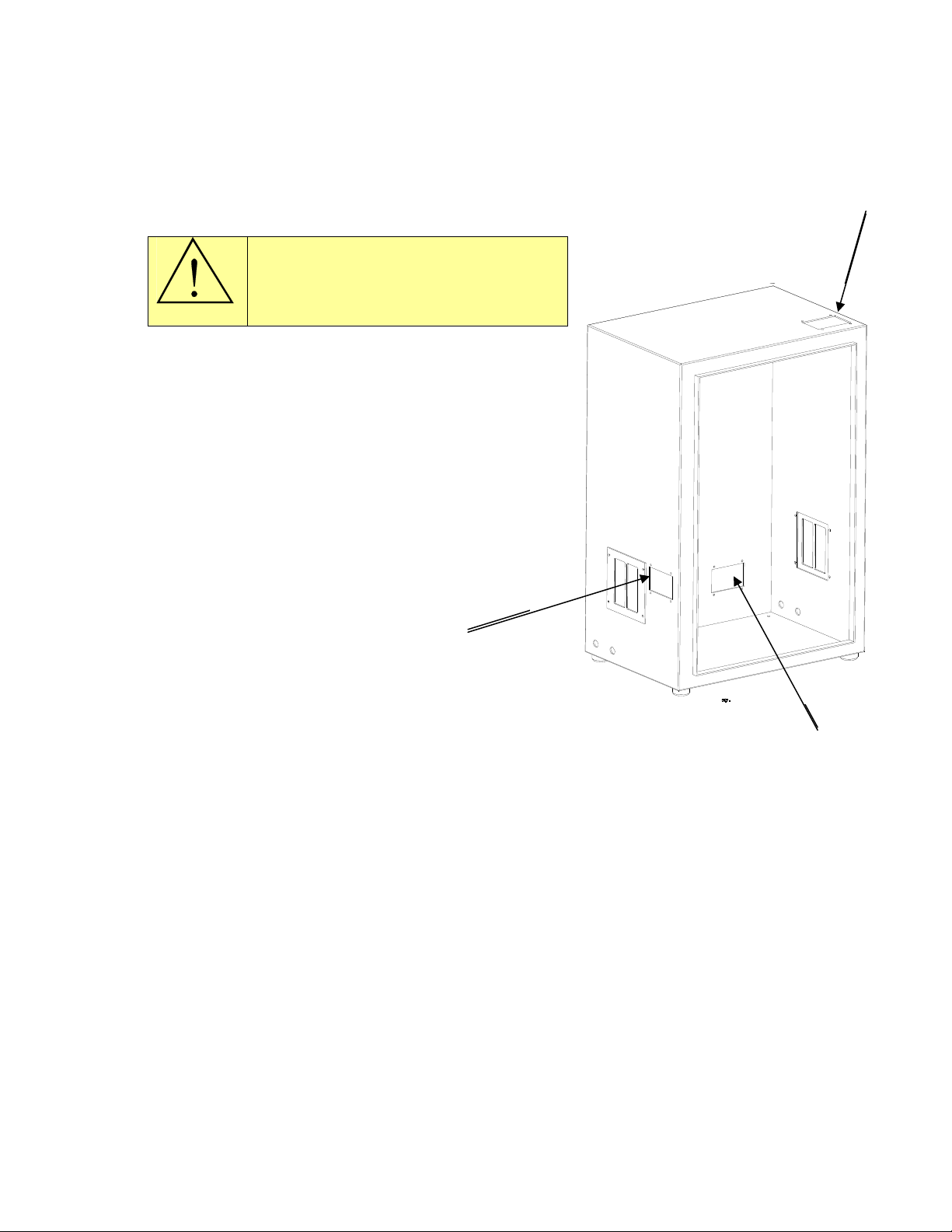
A hole needs to be punched in the cabinet of the
power supply for the supply voltage cable. It can
be done in one of two recommended locations.
The primary location (1) is on the left side of
cabinet next to left blank cover. The second
location (2) is at right side rear. Cut-outs in
cabinets will be available and cover plates will
be removable to make it easy for drilling holes
for power cables.
1
(3) A third cutout is provided for control
wiring.
2
3.2 Load
The load can be connected to the left or right side of the power supply. The unit is
shipped with the output on the right hand side. To change the output to the left hand
side, exchange the copper output blocks and covers between the two sides. The load or
cables connect to the output blocks. Ensure o-rings are used to avoid water leakage.
See Figure 2.
8

Figure 2: Output blocks mounting.
3.3 Cooling water
The cooling water can be connected to the left or right side of the power supply. The
unit is shipped with the water inputs on the left hand side. Two female ¼” NPT
connections are provided. If required, move the water fittings to the right hand side.
Keep the input towards the back of the unit and output towards the front of the unit
location. The unit will not operate if the water flow is reversed.
Turn on the cooling water flow and verify that it meets the minimum requirements as
given in section 1.8. on page 5. Check for any water leaks on the inlet, outlet and
heating coil. Tighten connections if necessary. Also check for any water leaks inside the
unit that could have been caused by shipping, and tighten any hose clamps if
necessary.
9

4. Front panel description and operation
4.1 Front panel description
This section identifies and describes the various parts of the front panel.
1 2
3 5
6
7 8 9
4
10
1) Fault, Trip and Limit LEDs
2) Heat On/Off LEDs
3) Program Indicator
4) Time Indicator
5) Power Indicator
6) LCD display
7) Reset button
8) Heat switch
9) Power Knob
10) Program Buttons
Figure 3: Front panel layout.
10
Table des matières


