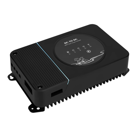
PowMr POW-M60-PRO Manuel utilisateur


1
Important Safety Instructions
WARNING: CAREFULLY READ AND FOLLOW ALL SAFETY INSTRUCTIONS
⚫Carefully read the manual before the controller is installed and operated; retain the manual in a
safe place for future reference.
⚫The controller must not be installed or operated by any of the following persons, unless they are
under strict instruction and supervision:
a. Anyone who lacks the appropriate knowledge, experience or competence, required for safe
installation and/or usage.
b. Anyone with compromised/reduced physical, sensory or mental capabilities, which may effect
safe installation and/or usage (including children).
⚫Controller installation and operation
a. There are no serviceable parts for this controller. Do NOT disassemble or attempt to repair the
controller.
b. Install the controller in a location with good natural airflow/ventilation and sufficient unobstructed
space around it; refer to the “2 Installation and Connection” section for more detail.
c. Install the controller on a non-flammable substrate and ensure there are no heat-sensitive items
in the immediate vicinity; it is normal for the controller to become hot during operation.
d. Install the controller in a location where it is protected from environmental conditions such as
direct sunlight, water, high moisture and dust, and also located well away from any flammable
liquids or gasses. Controller is for indoor use only.
e. Do not install or place/operate the controller on top of the battery, directly above the battery, or
in a sealed compartment with the battery; batteries can emit explosive gasses.
f. Do not cover or place any other items on top of the controller.
⚫Battery installation and charging
a. Install and charge the battery in a location with good natural airflow/ventilation.
b. Ensure that there are no ignition sources near the battery; batteries can emit explosive gasses.
c. Battery acid is corrosive; if battery acid comes into contact with skin immediately rinse with water.
d. Do not charge non-rechargeable batteries or Li-ion batteries if the battery temperature is below
0°C. Never charge a frozen battery.
e. Ensure that the unit is properly set up for the type of battery intended to be charged.

2
⚫Battery DC connections
a. Ensure that the DC system is fully shut down/isolated prior to disconnection of any existing
cabling and/or new connections are made to the battery/DC system.
b. Use flexible multi stranded copper cable with sufficient cross sectional area, line with an
appropriate fuse or circuit breaker; refer to the”2.4 Wiring Specification and Breaker Type”
section for more detail.
c. NEVER connect the solar panel array to the controller without a battery. Battery must be
connected first.
⚫Controller setup
a. Refer to the battery manufacturers instructions and specifications to ensure the battery is
suitable for use with this controller and confirm the recommended charge settings.
b. The integrated charge modes combined with adaptive charge logic are well suited for most
common battery types; such as flooded lead-acid, Gel and LiFePO4.

3
Important Safety Instructions........................................................................................1
1 Production Instructions ..............................................................................................4
1.1 Features .............................................................................................................5
1.1 Production Overview ..........................................................................................7
2 Installation and Connection........................................................................................8
2.1 Unpacking and Inspection ..................................................................................8
2.2 Preparing for Installation ....................................................................................8
2.3 Things You Need................................................................................................9
2.4 Wiring Specification and Breaker Type.............................................................10
2.5 PV Module Selection ........................................................................................10
2.6 Wiring Precautions ...........................................................................................11
2.7 Installation and Connection Step-By-Step........................................................12
3 Charging Mode ..........................................................................................................15
3.1 Alarm Function .................................................................................................16
4 Operation Instruction ................................................................................................17
4.1 Icon Display on LCD Screen ............................................................................17
4.2 Function Keys ..................................................................................................18
4.3 Browse and Configuration Step-By-Step..........................................................19
4.4 Working Mode ..................................................................................................22
4.5 Key Points Battery Parameter Settings ............................................................22
5 Protection...................................................................................................................24
5.1 Protection Provided..........................................................................................24
5.2 Troubleshooting................................................................................................25
5.3 Maintenance.....................................................................................................26
6 Technical Specification.............................................................................................27
Table of Contents

4
1 Production Instructions
Thank you for choosing the 0 layer Series of Solar Power Controllers. The controller uses numerical
control technology design, LCD display, automatic operation. Its maximum power point tracking
(MPPT) type battery charging mode, as well as control technology, will greatly extend the battery life.
The controller features a smart tracking algorithm that maximizes the energy from the solar PV
module(s) and charge the battery.
This controller is suitable for the solar energy system (independent system), control the charging and
discharging process automatically. The battery charging and discharging process of the controller is
optimized, which can prolong the battery life and improve the system performance. Its self-diagnostics
function and electronic protection function can avoid controller damage due to installation errors and
system failures.
The 0 layer series has a humanized LCD screen display algorithm, one interface to complete all
parameters display. Data can be monitored and configured in one layer of pages.

5
1.1 Features
⚫Integrated charge presets
Integrated charge presets combined with adaptive charge logic are well suited for most common
battery types, such as LiFePO4, Gel and flooded lead-acid.
⚫Flexible Application
Compatible with 12V/24V/36V/48V system voltage.
⚫Multi-stage charge algorithm
The multi-stage charge algorithm is specifically engineered to optimise each recharge cycle and
charge maintenance over extended periods.
⚫MPP Tracking Technology
The Maximum Power Point Tracking (MPPT) technology will track the array’s maximum power point
voltage (Vmp) as it varies with weather conditions, ensuring that the maximum power is harvested
from the array throughout the course of the day.
⚫High efficiency
Innovative MPPT technology with high tracking efficiency up to 99% and peak conversion efficiency
of 98%; resulting in lower power usage, less heat generated and cooler operation.
⚫Adaptive boost charge
Adaptive boost charge monitors the battery’s response during initial charging and intelligently
determines the appropriate boost charge duration for each individual charge cycle. This ensures
that the battery is fully recharged regardless of the discharge level or capacity and avoids excessive
time at the elevated boost charging voltage (that can accelerate battery aging).
⚫Durable and safe
i. Limit the maximum charging current. Protect battery performance and prolong battery life.
ii. PV array short circuit protection.
iii. PV input overcurrent protection.
iv. Controller overload protection.
v. Load short circuit protection.
vi. PV reverse polarity protection. No damage to the controller will result.
vii. Battery reverse polarity protection.
viii. Over-temperature protection. If the temperature of the controller heat sink exceeds 65℃, the
controller will automatically start reducing the charging current and shut down when
temperature exceeds 80℃.

6
⚫Silent operation
Almost silent operation since there is no cooling fan or moving parts, cooling is via natural
convection.
⚫Lithium battery activation
Compatible with Li-ion (LiFePO₄) batteries; when the battery type parameter is set to Lithium battery
the charge cycle settings are altered to suit. Moreover, when the connected lithium battery is in a
protected state, the controller will activate the lithium battery using the energy from the solar panel
with a current that does not exceed the lithium battery's protection voltage and current range.
Warning: Do not charge Li-ion batteries if the battery temperature is below 0°C.

7
1.1 Production Overview
①
LCD display screen
⑤
Load terminal
②
Function keys
⑥
Mount hole
③
PV input terminal
⑦
Heat sink
④
Battery terminal

8
2Installation and Connection
2.1 Unpacking and Inspection
Before unpacking the controller, check whether the package is damaged. After unpacking, check
whether thecontents of the package are damaged ormissing. You should have received thefollowing
items inside of package:
⚫Controller
⚫User manual
⚫Screws / bolts
2.2 Preparing for Installation
The controller range is designed to be wall mounted using the flanges which protrude from either
side of the heatsink.
Select the Mount Location:
Before mounting, the following aspects should be considered to identify/provide a suitable and safe
location:
a. Install the controller in a location with good natural airflow/ventilation.
b. Ensure there is sufficient unobstructed space around the controller; a minimum clearance of
75mm above and below is recommended.
c. Install the controller on a non-flammable substrate and ensure there are no heat-sensitive items
in the immediate vicinity; it is normal for the controller to become hot during operation.

9
d. Install the controller in a location where it is protected from environmental conditions such as
water, high moisture and dust, and also located well away from any flammable liquids or gasses.
e. DO NOT install or place/operate the controller on top of the battery, directly above the battery, or
in a sealed compartment with the battery; batteries can emit explosive gasses.
f. DO NOT cover or place any other items on top of the controller.
g. Install the unit by screwing four screws. It’s recommended to use M5 screws.
2.3 Things You Need
Make sure you have all the parts you need to install the controller:
Product
Quantity
POW-M60-PRO Controller (included)
1
DC-cable to connect the positive DC connection (+) of the controller to the positive
pole of the DC-distribution
3
DC-cable to connect the negative DC connection (-) of the controller to the positive
pole of the DC-distribution
3
DC breaker
3
Screws / bolts (Ø 5mm) to mount the cabinet to a surface. Use mounting materials
which are suitable to carry the weight of the controller. (included)
4
PV array. See section “2.5 PV Module Selection” for the configuration of solar panels
1
Battery pack.
1
NOTICE
For all wirings and circuits specifications see section “0
⚫Wiring Specification and Breaker Type”.
Table des matières
Autres manuels PowMr Contrôleurs