Polaris Automatic Gate Operators SL2000 Manuel utilisateur
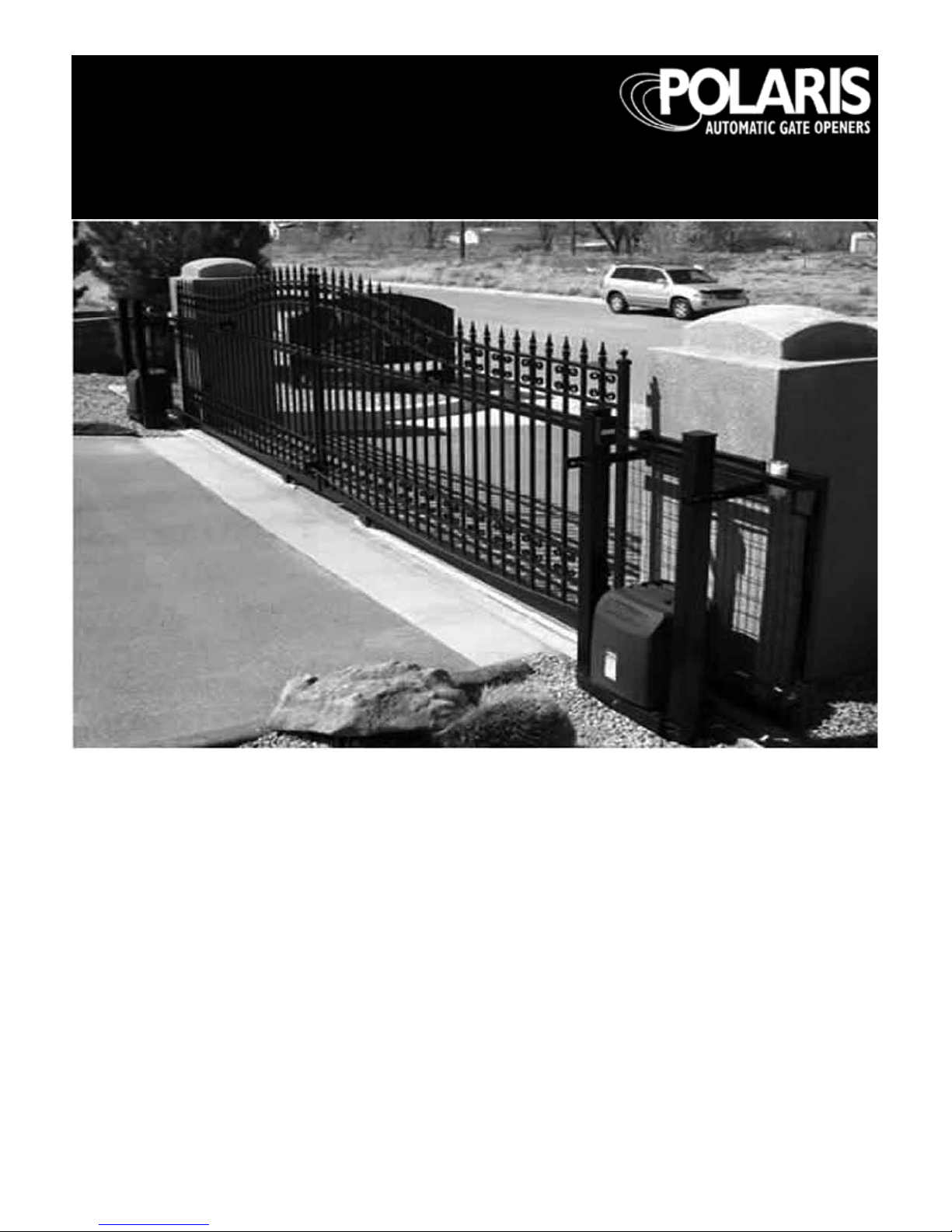
Automatic Slide Gate Operator
for models: Polaris SL2000
Polaris SL2500
Warning: Before installing your Polaris Automatic
Gate Operator (sometimes also referred to as the
“Product”), read this entire Installation Manual
for information about Product safety matters and
proper use of the Product. Only use the Product for
the purpose of operating a automatic driveway gate.
Installation Manual
WARNING OF RISKS, PURCHASER’S RESPONSIBILITIES, AND ASSUMPTION OF CERTAIN RISKS:
The directions for installation and use of the Product must be followed carefully. It is impossible to eliminate all risks inherently
associated with use of the Product. The eectiveness of the Polaris Automatic Gate Operator depends on proper installation and
the manner of use or application, all of which are beyond the control of Polaris Professional Gate Opening Systems or the seller. All
such risks are assumed by the purchaser, and by the purchaser’s installation and use of the Product.
The Polaris Automatic Gate Operator is for use on driveway gates only. The Product meets or exceeds the requirements of UL 325,
the standard that regulates gate operator safety, as established and made eective March 14, 2003, by Underwriters Laboratories,
Inc.
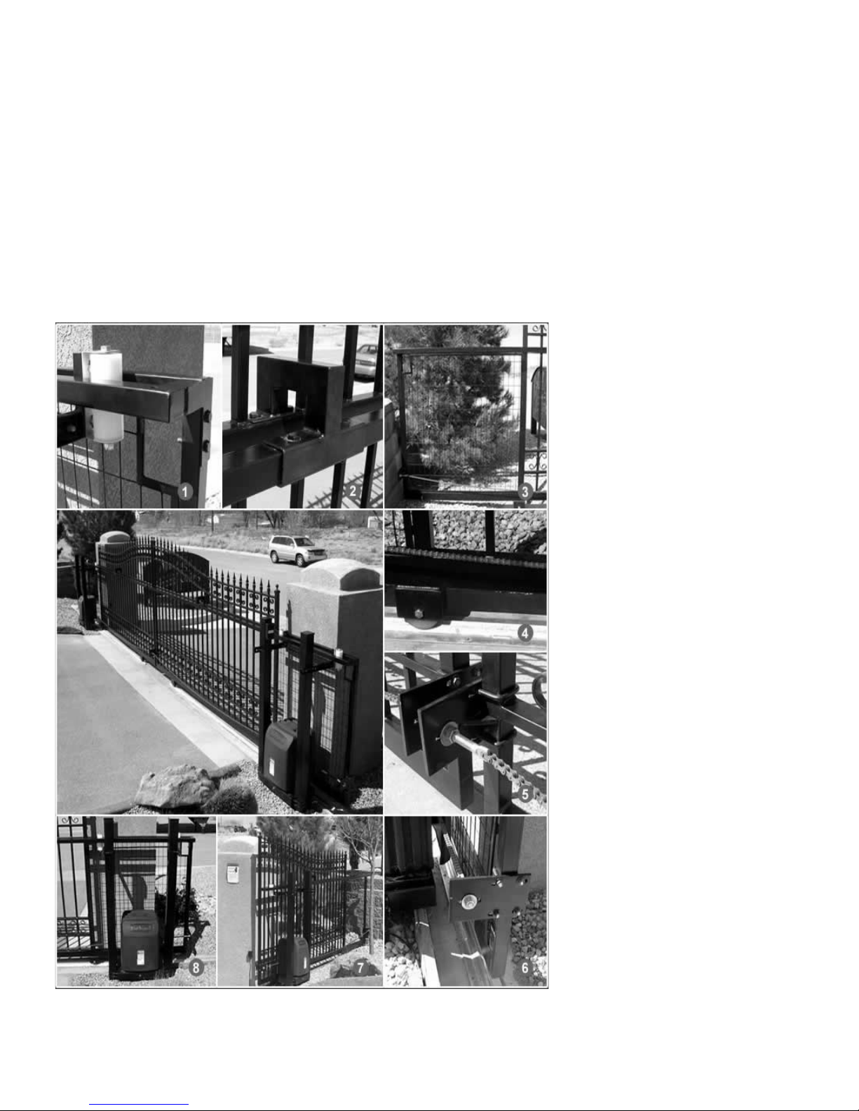
1. Heavy Duty Rollers
2. Guide Rail
3. Frame Extension
4. V-Track
5. Chain attach brackets
6. Heavy Duty Chain
7. Frame Extension
8. Built-in Gate Opener Platform

TABLE OF CONTENTS
GateOperatorClassCategories ................................. page4
WarningsandPrecautions....................................... page5
InstallationInstructions......................................... page7
WiringandHookupInstructions................................. page9
DIPSwitches...................................................page16
AccessoryHookUpDiagram ...................................page17
PartsListandIllustrations......................................page18
TechnicalSpecications........................................page19
Troubleshooting/Maintenance . . . . . . . . . . . . . . . . . . . . . . . . . . . . . . . . . page 20
ListofAccessories..............................................page21
Warranty ......................................................page22
Polaris Automatic Gate Operators
608 Tierra Montana Loop
Bernalillo , NM 87004
Phone: 877-313-8902
Fax: 800-830-3952
Email: ask@polarisgate.com
Web: www.polarisgate.com

4
GATE OPENER CLASS CATEGORIES*
The Polaris Automatic Gate Operator is intended for use with
vehicular slide gates. The opener can be used in Class I, Class
II, Class III and Class IV applications.
Residential Vehicular Gate Operator–Class I: A vehicular
gate opener (or system) intended for use in a home
of one-to-four single family dwelling, or a garage or
parking area associated therewith.
Commercial/General Access Vehicular Gate Operator–
Class II: A vehicular gate opener (or system) intended
for use in a commercial location or building such as
a multifamily housing unit (ve or more single family
units), hotel, garages, retail store or other building
servicing the general public.
Industrial/Limited Access Vehicular Gate Operator–Class
III: A vehicular gate opener (or system) intended for use
in an industrial location or building such as a factory or
loading dock area or other locations not intended to
service the general public.
Restricted Access Vehicular Gate Operator–Class IV: A
vehicular gate opener (or system) intended for use in
a guarded industrial location or building such as an
airport security area or other restricted access locations
not servicing the general public, in which unauthorized
access is prevented via supervision by security personnel.
*Categories established by Underwriters Laboratories for
vehicle gate operators
GATE OPERATOR CLASS CATEGORIES

5
WARNINGS AND PRECAUTIONS
General Safety Information
The Polaris Automatic Gate Operator is designed to provide
for safe operation. One of the most important safety features
of the gate opener is obstruction sensing. When there is
an obstruction that prevents the gate from opening or
closing, the gate will immediately reverse direction and
return to the fully open or closed position. While in the
process of returning to the fully open or closed position,
if the gate senses an additional obstruction the gate will
stop immediately and sound an alarm. At this point the
gate operator will need to be reset by turning the power
switch located on the inside of the cabinet frame to OFF
for a minimum of ten seconds. Should battery back up be
attached, the red wire from the battery will also need to be
disconnected for the same ten seconds.
The gate operator includes an adjustment for setting the
sensitivity of the obstruction performance. Refer to page
12 for Obstruction Sensitivity Set Up details.
Slide gates are large heavy objects. Automatic gate
openers provide a convenient way to open and close the
gates. Since the gate system and its components exert a
high level of force to open and close the gate, they can
be dangerous, causing severe injuries or death to you
and others.
Your safety and the safety of others depend on the
installer of this system to read, understand, and follow
the information and instructions in this manual.
The Polaris Automatic Gate Operator is designed to comply
with UL 325, the safety standard covering automatic gate
opening systems. UL 325 requires that gate opening
systems have provisions for, or be supplied with, at least
one independent primary and one independent secondary
means of protection against entrapment. The primary
means of entrapment protection in the Polaris Automatic
Gate Operator is Type A, an inherent means of entrapment
protection. The secondary means of entrapment protection
in the Polaris Automatic Gate Operator is Type B1, the
provision for the connection of a photo cell or other non
contact sensor.
The gate operator’s built-in means of entrapment
protection (Type A) may not be sensitive enough to
prevent bodily injury in some circumstances. Secondary
means of entrapment protection (Type B1), such as a
photo cell are suggested for enhanced safety.
Safety overview checklist:
WARNING – Moving gate has potential of inicting
injury or death–do not start gate unless path is clear.
WARNING – To reduce the risk of injury or death:
• Use this operator only with slide gates.
• READ AND FOLLOW ALL INSTRUCTIONS.
• Never let children operate or play with gate controls.
Keep the remote control away from children.
• Always keep people and objects away from the gate.
NO ONE SHOULD CROSS THE PATH OF THE MOVING
GATE.
• The entrance is for vehicles only. Pedestrians must use
a separate entrance.
• SAVE THESE INSTRUCTIONS
• Remember that the Polaris Automatic Gate Operator
must only be installed on gate systems meeting the
requirements of the application.
• Ensure that you are using the correct opener for the
type and size of gate, its frequency of use and the class
rating.
• Ensure that the gate and gate operator installation
comply with applicable local codes.
• Contact local re and law enforcement to arrange
emergency access procedures.
• Persons are to keep clear! The gate is able to move
without prior warning. Do not let children operate the
gate or play in the gate area.
• Use caution with moving parts to avoid injuring ngers
or hands.
• Consider installing contact sensors, or non-contact
sensors to provide additional safety and protection
against entrapment.
• Never activate the gate opener until you ensure that
the area is clear of people, pets, or other obstructions.
Watch the gate until it stops.
• Controls must be far enough from the gate so that the
user is prevented from coming in contact with the gate
while operating the controls.
• Keep gates properly maintained. Read the owner’s
manual. Have a qualied service person make repairs
to gate hardware.
• Test the gate monthly. The gate MUST reverse on
contact with a rigid object or stop when an object
activates the non-contact sensors. After adjusting the
force or the limit of travel, retest the gate operator.
Failure to adjust and restest the gate operator can
increase the risk of injury or death.
WARNINGS AND PRECAUTIONS
6
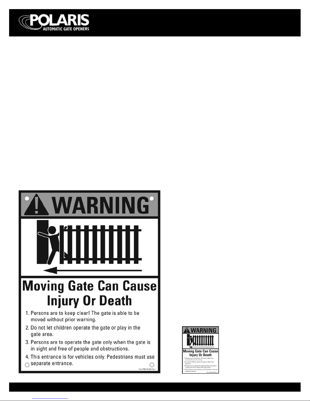
Figure 2
Warning signs (two enclosed) to be installed
on each side of the gate (three to ve feet
above the bottom of the gate)
Install warning decals,
one on each side of gate
operator
Entrapment Alarm
(UL 325; 30.1)
In compliance with UL 325 the Polaris Automatic Gate
Operator is designed to stop and reverse direction within
two seconds of sensing an obstruction. In addition, the
Polaris Automatic Gate Operator activates an audible alarm
if the unit incurs an obstruction twice while opening or
closing. This alarm sounds for ve minutes, or until the
opener receives a renewed, intended input from a hardwired
control such as the Push Button Control. At that point the
gate returns to a fully open or fully closed position. Should
there be no means of sending the operator a renewed,
intended input, the gate operator can be reset by turning
the power switch located on the inside of the cabinet frame
to OFF for a minimum of ten seconds. Should battery back
up be attached, the red wire from the battery will also need
to be disconnected for the same ten seconds.
Figure 1
WARNINGS AND PRECAUTIONS
Warning Signs and Labels
Required Safety Precautions for Gates
Warning signs alert people of automatic gate operation.
They are required when installing the Polaris Automatic Gate
Operator. If pedestrians will be in the area, install a walk-
through gate for their use.
Warning Signs
The warning signs must be installed on both sides of the
gate.
These warning signs and labels must be used. If any
were missing when the gate operator was purchased,
immediately contact Polaris Automatic Gate Operators
for replacements.
7
INSTALLATION INSTRUCTIONS
Concrete Pad
• Pour concrete pad a minimum size of 24” x 24” at
least 6” above ground
• Be certain that concrete base is placed below frost line.
Check local building codes.
• Operator frame can be fastened to the concrete pad
using four 4½”x 4” concrete expansion bolts.
• Necessary electrical conduit can be placed in the
concrete pad area prior to adding concrete. Align with
the hole in the bottom of the chassis.
• Nominal distance between the gate and chassis is 5”
(see g. 6).
Post Mounting
• Drill three holes through 2” x 2” steel posts for
mounting 3/8” x 3” galvanized steel bolts with washer
and nut (posts, bolts, washers, and nuts all purchased
separately).
• When post mounting operator, be sure to cover the
bottom opening in gate frame which is normally used
for electrical conduit when pad mounting.
• Nominal distance between the gate and chassis is 5”
(see g. 6).
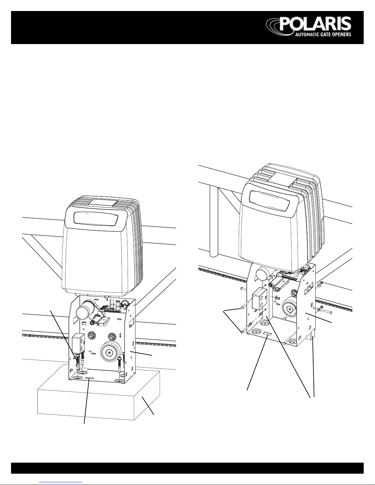
Figure 3
INSTALLATION INSTRUCTIONS
SLIDERfig4
Figure 4
Steel posts
(not included)
SLIDERfig3
Concrete pad,
6” above ground
Access hole for electrical connection
Chassis
4½” x 4” concrete
expansion bolts
Access hole for
electrical connection
Chassis
3/8” x 3”
galvanized steel
bolts (not
included)
8
SLIDERfig5
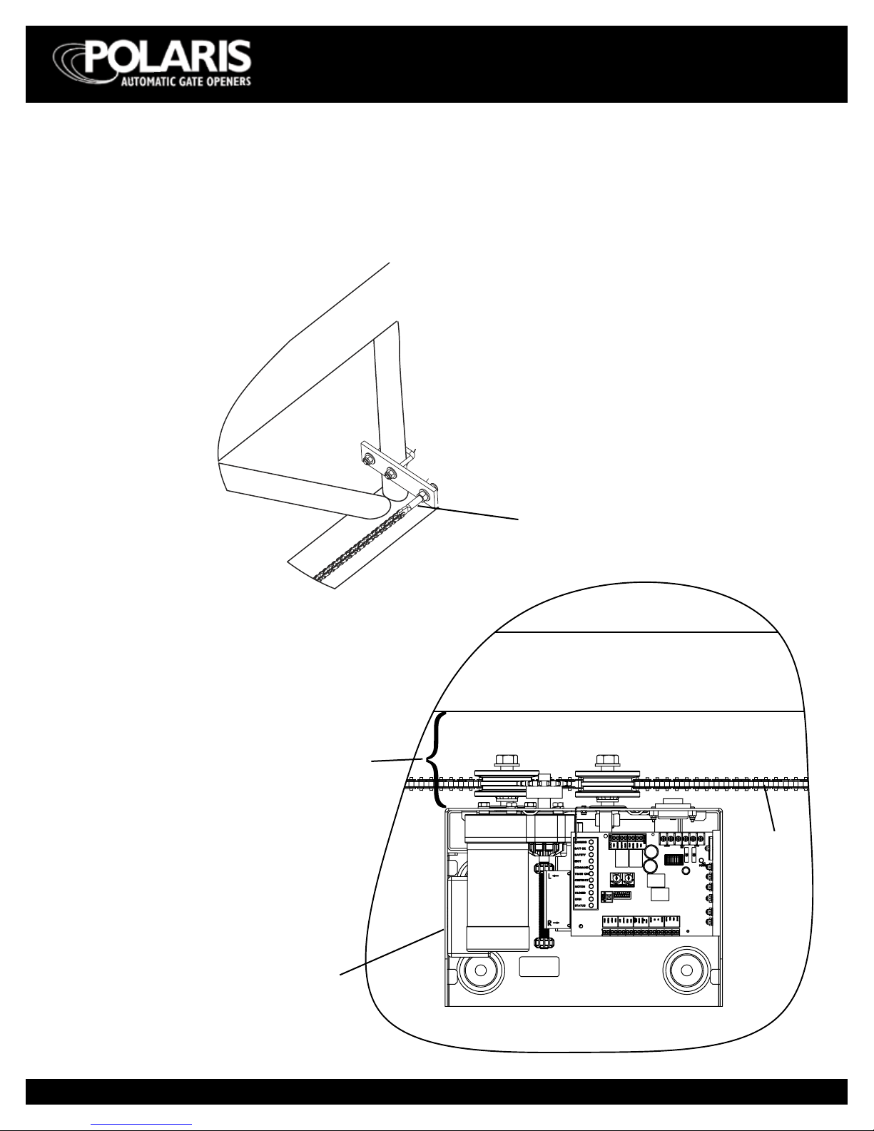
Figure 5
Tension screw
Figure 6
Gate
Chain
Chassis assembly
5” ± ¼”
Chain Installation
• Make sure the tension screw does not extend beyond
the outside edge of the gate frame.
• Make sure the holes in the chain bracket are level with
bottom of idler wheels.
INSTALLATION INSTRUCTIONS
9
WIRING AND HOOKUP
INSTRUCTIONS
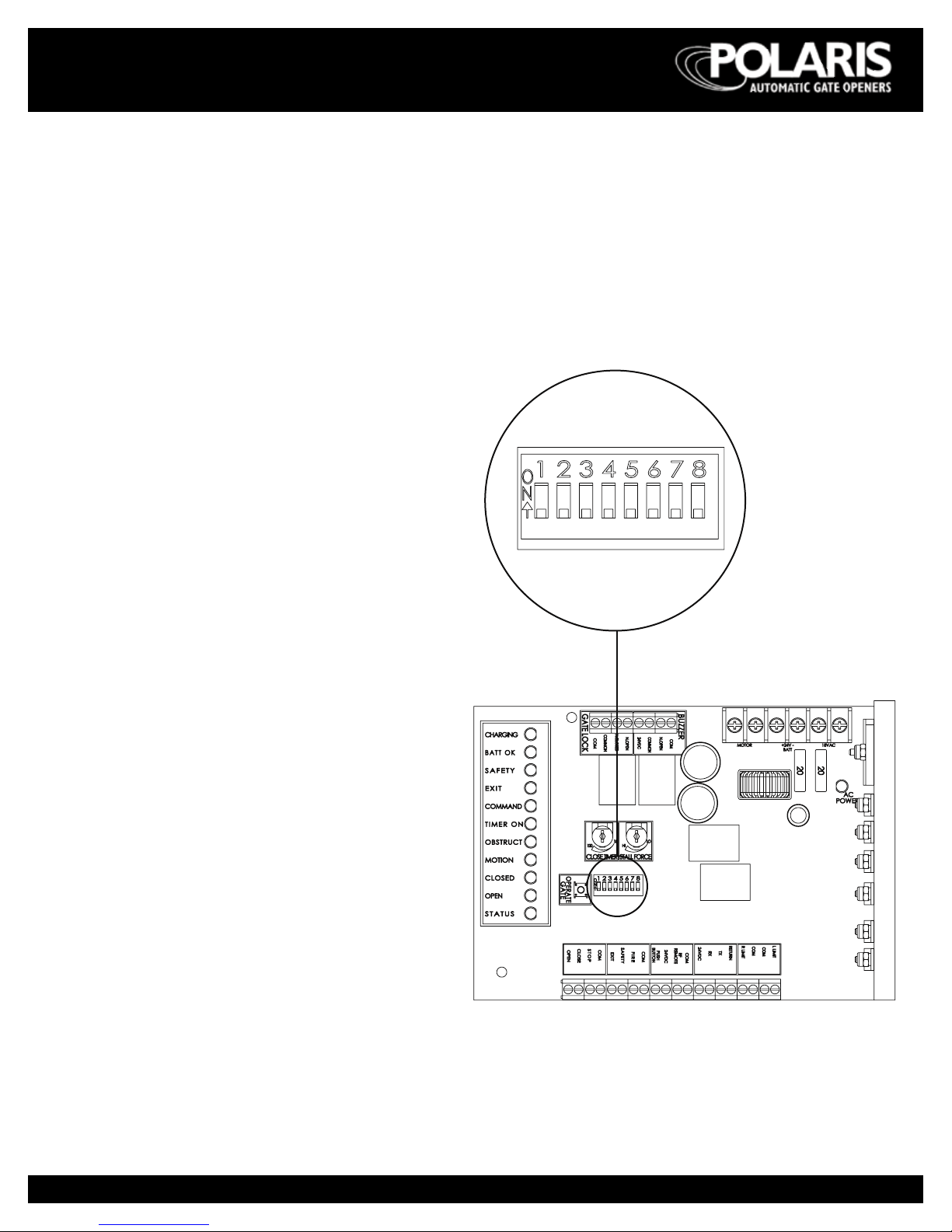
Select Gate Movement Direction
Standing inside of the property and looking out, if gate
operator is on the right select “right” hand operation –
DIP switch 1 to OFF position.
Standing inside of the property and looking out, if gate
operator is on the left side select “left” hand operation –
move DIP switch 1 to ON position.
Figure 7
WIRING AND HOOKUP INSTRUCTIONS
NOTE: All DIP switches are
shown in the factory default
position (OFF).
10
Connecting to 110 Vac electrical power
IMPORTANT NOTE: All electrical connections must be
performed by a licensed electrician.
• Each gate operator should be electrically attached to
its own 20 amp circuit breaker.
• Connect AC power directly to the three wire pigtails
extending from the duplex receptacle located inside
operator cabinet.
Wire Color/Description:
Green = Ground
White = Neutral
Black = Hot
WIRING AND HOOKUP INSTRUCTIONS
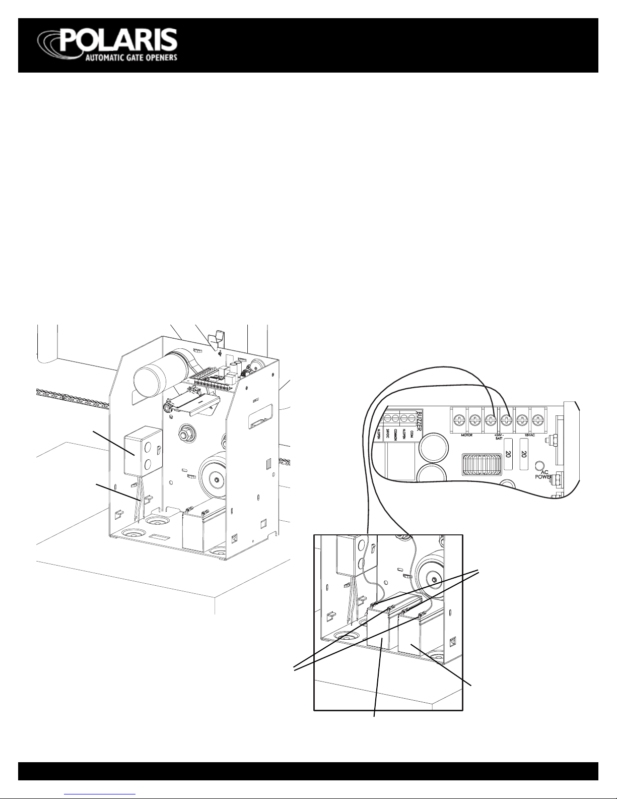
Connecting battery back-up
• Gate operator will operate without batteries attached.
• If desired, automatic operation for a short period of
time upon loss of power can be achieved. Install two
12 volt DC batteries (purchased separately).
• Batteries must be connected in series to ensure 24V.
• Connect batteries to circuit board as follows:
Battery 1 + to + 24V Battery terminal
Battery 1 - to Battery 2 +
Battery 2 - to - 24V Battery terminal
NOTE: Operator cannot be powered o unless batteries
are disconnected.
figure-power-switch
Connecting
wires
Duplex
receptacle
Figure 8
Figure 9
SLIDERfig8
Circuit board
Battery 1
Battery 2
- (black) terminals
+ (red) terminals
Ce manuel convient aux modèles suivants
1
Table des matières
Autres manuels Polaris Automatic Gate Operators ouvre-porte


