085 501 821q 9 30007-008-1q
8. Special Versions
8.1 DS 5 + DS 10 -DNV-Version
These sounders have been designed and certied in accordance with the Guideline of DNV. Special demands are made on
the stability when exposed to environment al inuences and on electromagnetic compatibility (EMC).
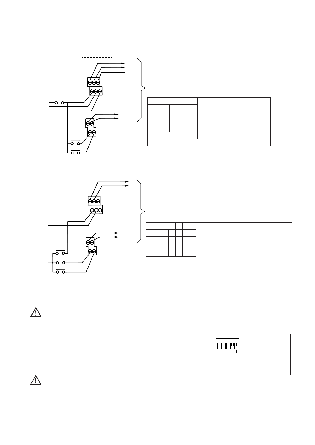
8.2 Special versions for explosion hazard zones 2 and 22: DS 5 -3G/ 3D and DS 10 -3G/ 3D
These sounders are suitable for use in an explosion-hazard environment in zones 2 acc. to EN 60079-10-1 and 22 acc. to
EN 60079-10-2. The sounders can be used for gases of the temperature classes T1, T2, T3 and T4 as well as for environments
with non-conductive dusts.
The surface temperature of the housing does not exceed +135°C.
Standard conformity: Guideline 2014/34/EU (ATEX)
EN IEC 60079-0
EN IEC 60079-7
EN 60079-31
Identication marking: II3G Ex ec IIC T4 Gc -25°C ≤Ta ≤+55°C (all voltages except 24V AC)
PDG 03.0001 X II3G Ex ec IIC T3 Gc -25°C ≤Ta ≤+55°C (only 24V AC)
II3D Ex tc IIIB T135°C Dc IP66/67 -25°C ≤Ta ≤+55°C
The sounders are available for operating voltages 12V DC, 24V DC, 12V AC, 24V AC, 115V AC, 230V AC.
Installation requirements:
The sounders are to be installed in conformity with current editions of the appropriate parts of DIN EN 60079 or in accordance
with equivalent IEC specications.
EN 60079-10-1 Explosive atmospheres - Part 10-1: Classication of areas - Explosive gas atmospheres
EN 60079-10-2 Explosive atmospheres - Part 10-2: Classication of areas - Combustible dust atmospheres
EN 60079-14 Explosive atmospheres - Part 14: Electrical installations design, selection and erection
Applicable national constructor provisions are to be observed in the case of all work on the sounder.
In the case of work in explosion-hazard areas, the safety of persons and equipment depends upon adherence to all of the
relevant safety regulations. The following is to be observed:
- Equipment Safety Act
- National safety regulations
- National accident prevention regulations
- National construction and erection regulations
- Generally accepted rules of technology
- Characteristic values of the sounder according to the
rating plate and the operating instructions
Special application conditions X
The sounders are designed to be used in stationary installation. When using the original cable gland a strain relief for the
connecting cable has to be ensured. The cable gland is restricted for applications with a low degree of mechanical hazard
according to EN IEC 60079-0. If a protected installation is not possible Ex-e cable glands without restriction combined with a
connection thread gasket have to be used.
Minimum requirement : M20x1,5, IP66/67, II3G Ex e IIC Gc / II3D Ex tc IIIB Dc, Tamb. -25°C .. +70°C.
Original cable gland: WISKA ESKE/1-e 20, sealing range 7 - 13mm, PTB 13 ATEX 1015 X.
Use in areas with a risk of dust explosion:
If the device is exposed to heavy charge-separating processes, dangerous electrostatic charges can occur. Charge-sepa-
rating processes are, for example, direct exposure to pneumatic transport media. By experience, manual processes do not
generate heavy charges.
- Avoid heavy charge-separating processes at the installation site and during cleaning.
- Recommendation: Install the device out of range of persons.
- Prevent touching with objects.
- Clean only with water or damp cloths.
- Avoid unintentional and dry rubbing.
- Do not clean with compressed air, high-pressure or steam jets.
- Earth the device housing.
Further Notes:
The type of protection IP 66/67 must be established after installation by means of proper and correct closing of the casing
and the use of matching cables and screwed cable glands. The sealing range of the screwed cable gland is to be adhered
to. (Original cable gland: 7 - 13mm.) The cable gland is only designed for sheathed cables. During installation the seal of the
housing is to be checked for damage and function. Damage can cancel out the explosion protection.
Tighten the housing screws (Torx-T20) with a torque of approximately 2 - 2,5 Nm in at least two passages crosswise.
Do not cover the opening of the bell mouth during operation otherwise too high surface temperatures may occur.
The opening of the bell mouth must not point upwards after installation. Replacement of the device after ten years is recom-
mended.
150 [5.91"]
133.5 [5.26"]
Blindstopfen M20
Blanking plug M20
Boîte à bourrage M20
M20x1,5
Ø7 [0.28"] 143 [5.63"]
Vite cieca M20
Blanking plug M20