PF FF9000 Manuel d'instructions
Parking and access control equipment manufactured in the UK
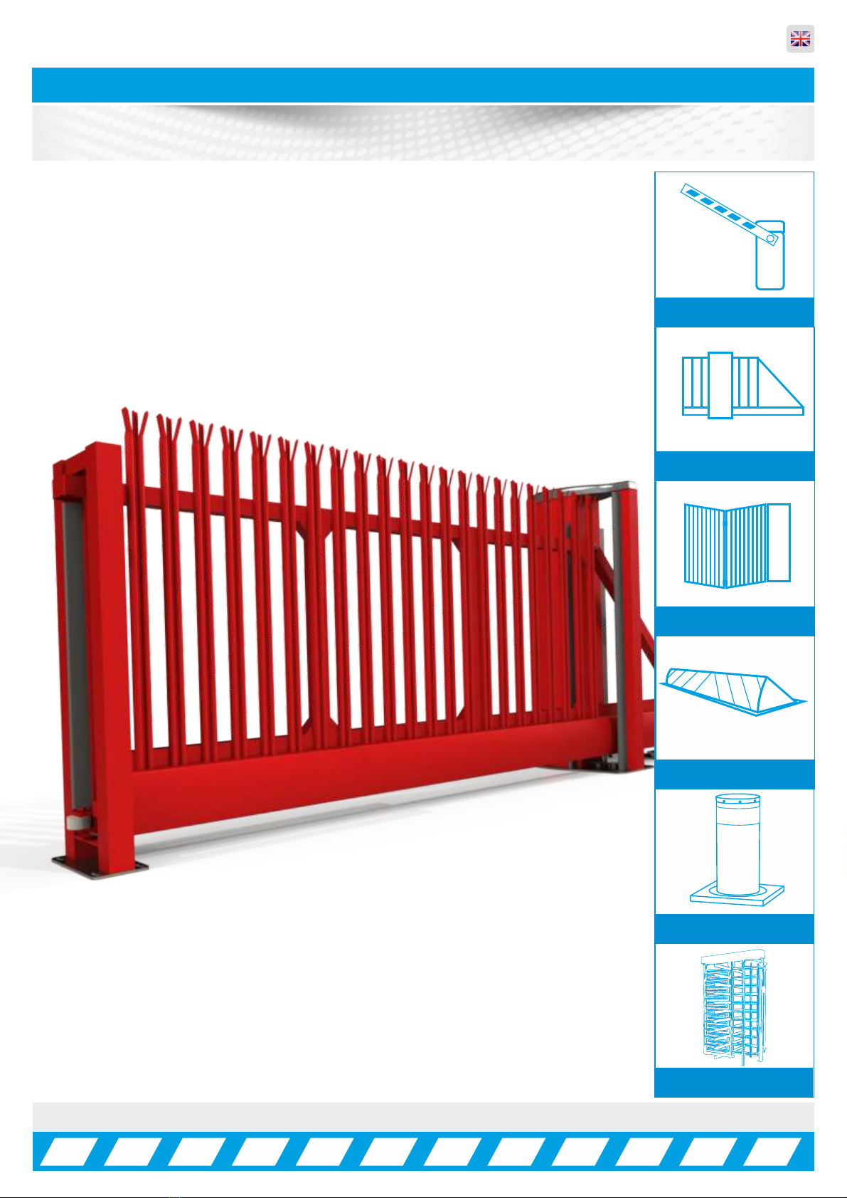
FF9000 Automatic Sliding Gate
Rev:8.0
Manual Barriers
Auto Sliding Gates
Auto Bi-Fold barriers
Auto Rising Kerbs
Turnstiles
Auto Rising Bollards
Installation, Operation &
Maintenance Manual
in Parking and access control equipment manufactured in the UK
Automatic Sliding Gates
INDEX ... Page No:
HEALTH & SAFETY INFORMATION 03
DELIVERY, MOVEMENT & TRANSPORT 04
COMPONENT IDENTIFICATION 05 - 07
PLC TIMER PROGRAMMING 08
OPENING & CLOSING POSITIONS 09
GATE USAGE 10
PARAMETER LIST 11
TROUBLESHOOTING GUIDE 12 - 13
WIRING DIAGRAM 14
QUICK CONNECTION GUIDE 15
MASTER/SLAVE WIRING 16
WIRING & PROGRAMMING 17 - 20
LOOP DETECTOR SETTINGS 21 - 22
TROUBLESHOOTING GUIDE 23 - 24
POTENTIAL SYSTEM HAZARD AREAS 25
HANDING FORM 26
INSTALLATION & COMMISSIONING CHECK LIST 27
SERVICE LOG 28
COMMISSIONING CERTIFICATE 29
DECLARATION OF CONFORMITY 30
ELECTRONICS CERTIFICATE 31
2
in Parking and access control equipment manufactured in the UK
Automatic Sliding Gates
Introduction and Warnings
3
This equipment is part of a large range of traffic flow products. They are designed to be easy to install, as
all settings and internal wiring has been completed in our factory. Any of the instructions in this manual
should only be carried out by a qualified service engineer or a competent person.
The gates are ready to bolt down, connect in the single phase supply and any loops etc and then power
up. In this manual there is important information on how to do this, but most importantly of all how to do
this safely. Please approach any task responsibly and safely.
The following information is a guide only, and whilst we have made every effort to be accurate and correct
there may be printing errors which we cannot be held responsible for.
With a correct installation you can expect to enjoy many years of reliable service from this product, we do
however recommend that the product has a bi-annual service carried out by an engineer. Please contact
our service department to obtain a quote. As we manufacture the products we are best suited to care for
your equipment.
Thank you for your custom and welcome to the exciting world of Total Traffic Flow Solutions.
/ /20
!
Important Safety Notice
Sliding Gates are designed to Control the flow of vehicular traffic
primarily. It can be dangerous to allow the passage of
pedestrians and any other self-powered animal or device to
utilise this method of access without appropriate warnings and or
signage.
It may be necessary for the end user of this product to provide
an alternative, safe method of access to cater for the previously
mentioned categories.
The end user should fit all necessary signage and warning
notices to either side of the gate, which should be visible and
clear from all directions of approach.
The product that was shipped to you was designed with a control
program to protect all categories from harm or affect this
however is only a fail safe and should not be modified or
tampered with by any unauthorised person not sanctioned by the
manufacturer.
Please sign and date below to say that you have read and
understood this notice before ANY installation work:
The “Warnings” leaflet and “Instruction booklet” supplied with this
product should be read carefully as they provide important information
about safety, installation, use and maintenance.
Scrap packing materials (plastic, cardboard, polystyrene etc) according
to the provisions set out by current standards. Keep nylon or polystyrene
bags out of children's reach.
Keep the instructions together with the technical brochure for future
reference.
This product was exclusively designed and manufactured for the use
specified in the present documentation. Any other use not specified in
this documentation could damage the product and be dangerous.
The Company declines all responsibility for any consequences resulting
from improper use of the product, or use which is different from that
expected and specified in the present documentation.
Do not install the product in explosive atmosphere.
The construction components of this product must comply with the
following European Directives: 89/336/CEE, 73/23/EEC, 98/37/EEC
and subsequent amendments. As for all non-EEC countries, the abovementioned
standards as well as the current national standards should
be respected in order to achieve a good safety level.
Information on using
this manual
ŸRead all information thoroughly
ŸPay attention to all safety advice
ŸBe aware of the symbols (shown above right and
above left) as they have different meanings. One is an
information symbol, the other a warning.
ŸThere are many artists impressions of the product in
this manual you should refer to the images as a guide
only. Professional CAD drawings should be used as
a reference drawing and nothing else. As before every
effort has been made to be 100% accurate in this
manual but we cannot make any guarantees.
ŸAs we constantly innovate our products we may
change the quoted spec and any other details that
have been documented in this manual so you should
always refer to the supplier to see if the manual that
was shipped with your product is the latest edition.
ŸAs with all electrical installations you should use a
qualified electrician and obey all of the latest laws and
regulations.
ŸBe sure to fill out and complete ALL paperwork where
instructed as this manual is the equipments log book
and maintenance manual.
The Company declines all responsibility for any consequences resulting
from failure to observe Good Technical Practice when constructing
closing structures (door, gates etc.), as well as from any deformation
which might occur during use.
The installation must comply with the provisions set out by the following
European Directives: 89/336/CEE, 73/23/EEC, 98/37/EEC and
subsequent amendments.
Disconnect the electrical power supply before carrying out any work on
the installation. Also disconnect any buffer batteries, if fitted.
Fit an omnipolar or magnetothermal switch on the mains power supply,
having a contact opening distance equal to or greater than 3mm.
Check that a differential switch with a 0.03A threshold is fitted just before
the power supply mains.
Check that earthing is carried out correctly: connect all metal parts for
closure (doors, gates etc.) and all system components provided with an
earth terminal.
Fit all the safety devices (photocells, electric edges etc.) which are
needed to protect the area from any danger caused by squashing,
conveying and shearing, according to and in compliance with the
applicable directives and technical standards.
in Parking and access control equipment manufactured in the UK
Automatic Sliding Gates
Delivery, Movement & Transportaton
4
This article describes how your equipment will be delivered to you, specifications on the transportation
used and advice including health & safety on movement of the equipment.
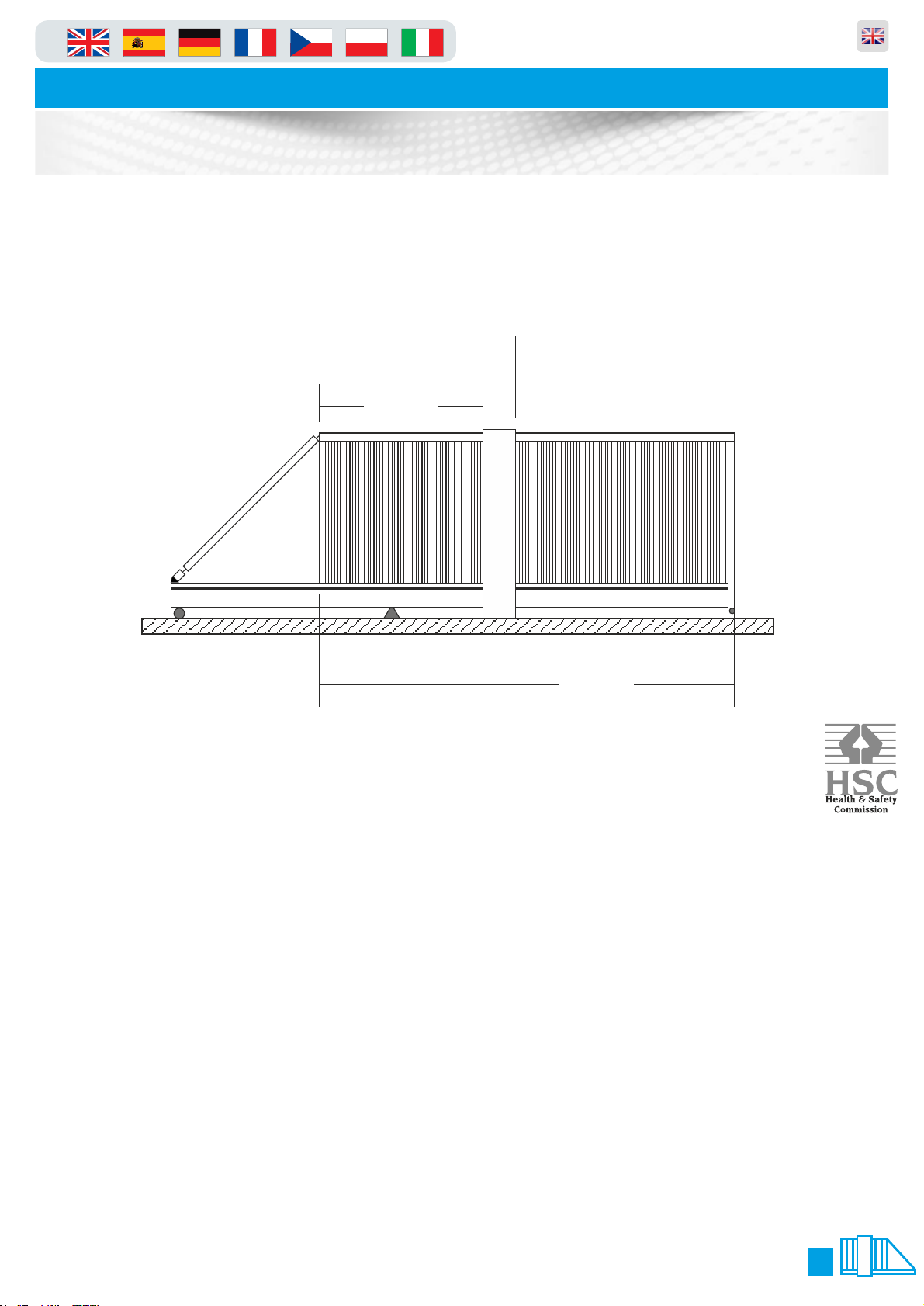
The gate should ALWAYS! be in the central position before any movement commences, this ensures that
the gate does not distort or get damaged. Refer to Manual Release instructions on Page 6 of this manual
to move the gate into this position.
Illustration shows gate central to main tower
The manufacturer will use a qualified transport company to deliver the product conforming to the
necessary regulations as detailed below:
ŸAll drivers are qualified hi-ab certified
ŸAll drivers are tested once yearly
ŸAll drivers carry risk assessments and method statements (available on request)
ŸThey are controlled under law to conform as there are no trade regulation standards to comply with
Health and safety Considerations:
Moving Goods Safely (MGS) is a national project involving both the Health and Safety Executive (HSE) and
Local Authorities (LA) working in partnership. The project aims to reduce injuries and ill-health arising from the
movement of goods from supplier through haulier to the recipient and end user including any home deliveries.
The project will focus upon the delivery and collection of goods and the hazards this generates. It covers the
main areas that cause the majority of injuries and ill-health to workers, including:
ŸWorkplace transport;
ŸSlips & trips, and;
ŸMusculoskeletal disorders (MSD).
The movement of goods presents us, as health and safety regulators, with the challenge of dealing with a huge
variety of issues. The commercial organisations involved within the movement of goods are diverse including
haulier, third party logistics providers, pallet networks, retailers etc, with some very large companies,
thousands of small businesses and the self-employed. The movement of goods is more than just trucks on the
road with a large proportion of accidents happening at the delivery/collection sites that are often not directly
under the control of the company making the delivery or collection. Communication and cooperation problems
can arise due to the many organizations involved in the movement of the goods, and this can also lead to
difficulties in effectively managing health and safety.
(Source H&S Executive UK 2008)
37
7
94
50
3.
1. 2.
4.
Lifting Point Catch Post
45 mins
60 5
10
15
20
25
30
35
40
45
50
55
in Parking and access control equipment manufactured in the UK
Automatic Sliding Gates
Component Identification & Notes
5
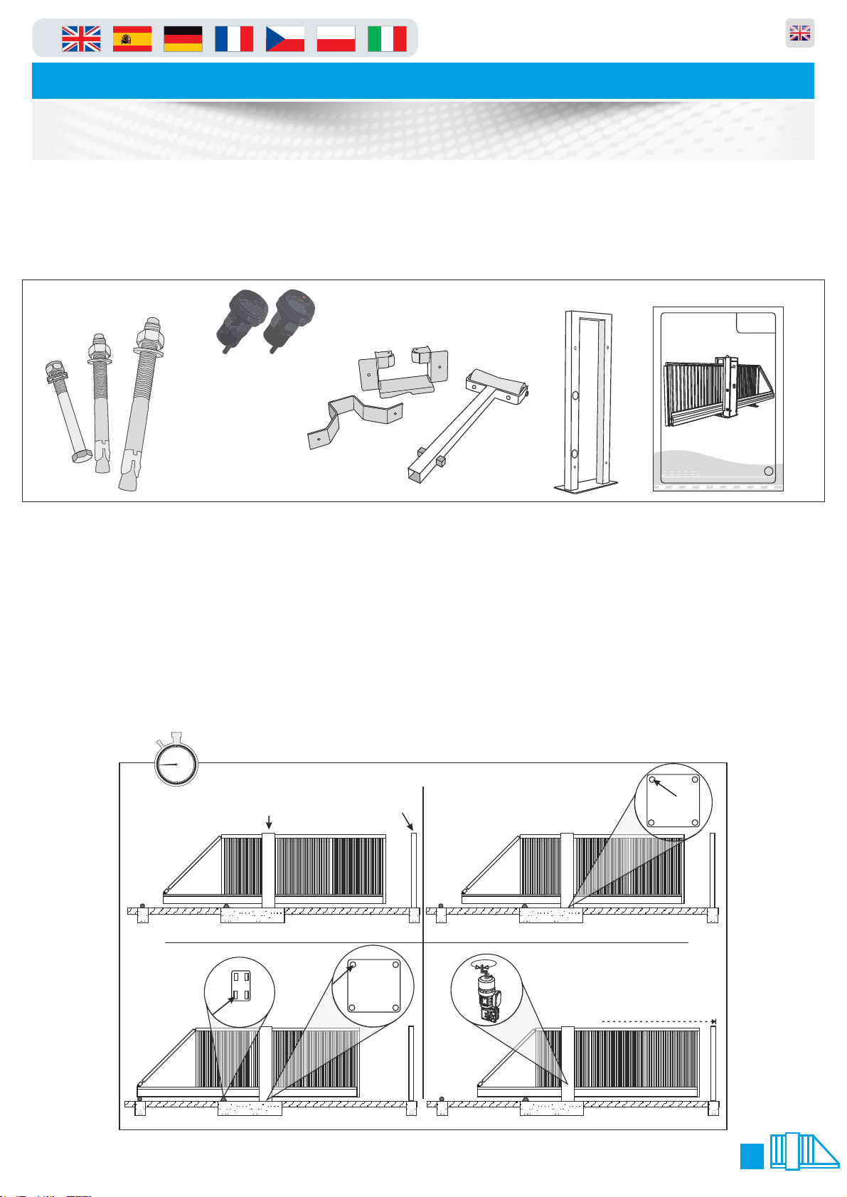
1. When delivered, the gate is locked in a central position so that the gate is
balanced when lifted from the top of the tower.
2. Lower the gate onto the plinth and visually align the gate and catch-post into position. Using one M20
fixing, bolt down the main tower using one of the rear bolt-down holes.
3. Making sure that the gate is still visually aligned, use one M16 fixing and bolt down the rear support
wheels (on the opposite side to the hole used on the main tower) see below.
4. Manually slide the gate into the closed position to fine tune the alignment of the gate with the catch
post.(See Page 6 for details on Manual Release)
The numbers in the text document below relate to the drawings below.
You should check that you have received the following in your order as they are referred to throughout this
manual (note this can change per gate spec i.e. manual components are different from automatic):
M16 Anchor
Catch Post
Bolt 4 No.
M16 Bolt
8 No.
M20 Bolt
4 No.
PF9000 A/M
PF9000 A/M
Automatic Sliding Gate
Manual Sliding Gate
Maximum Span: 10 Metres
Duty Cycle: 100% GB
O&M Manual
Revision 3.0
O&M Manual 1 No.
Catch post 1 No.
Photo Cells for
catch Post 2No.
Bottom catch
post bracket 1 No.
Rear external
roller 1 No.
Top catch post
bracket 1 No.
9.
5/6. 7/8.
10/11.
Central Position
45 mins
30mm Nut
30mm Nut
Spirit Level Co.
Beam shown
to be level
Receiver
Receiver
Transmitter
Transmitter
60 5
10
15
20
25
30
35
40
45
50
55
in Parking and access control equipment manufactured in the UK
Automatic Sliding Gates
Component Identification & Notes
6
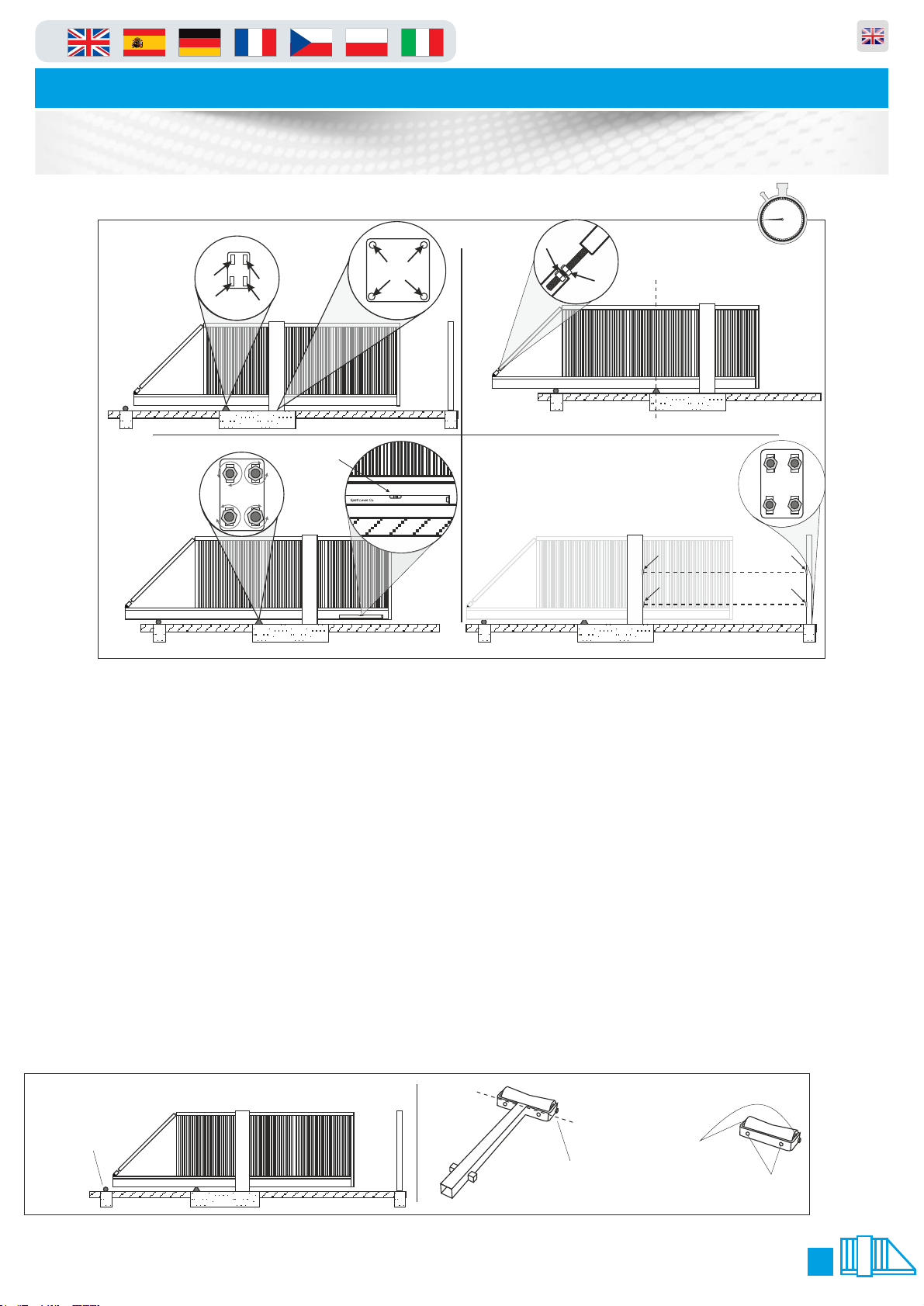
5. Manually slide the gate back into the central “balanced” position taking care
not to move the tower or rear wheel support base plate.
6. Finish bolting down the rear support wheel base-plate and the main tower of the gate
making sure that it is true and square in both directions.
7. Slide the gate until the centre of the lower main beam is in the centre of the rear support wheels and the
centre of the main tower i.e. have the lower main beam supported centrally by the rear support wheels
and the drive rollers.
8. Undo the 30mm nuts that lock the cantilever arm adjuster to relax the cantilever arm and leave the gate
in an unstressed state.
9. Placing a level on the centre of the lower beam or lower rail, adjust the rear wheel support until the
lower main beam is level. Manually pull the gate closed and adjust the cantilever until the gate is level.
10. Using a laser square or similar, make sure the photo-cells from the Main Gate Housing to the Catch
Post line up (this should be already level as it is governed by the plinth levels).
11. Now fit the two photo cells provided in the pre drilled holes and connect using the wiring diagram
(page 8). Once the Photo Cells have been connected, complete the installation of the Catch Post using 4
x M16 fixing bolts (supplied) making sure that it is true and square.
12. Now most important of all, you must fit the rear roller as shown (under the parts list on the previous
page), which is universal in the way it can be fitted. It can either be used as a “cast in” post, or the bottom
strut can be cut off and used as a “bolt down” roller all illustrated below.
12.
Bolt down or cast
the rear roller in this
position shown.
Cut along this line to
remove the bottom
spiggots and shaft.
Once the shaft is
removed you will
use the M16 bolts
to fix down.
Before you can bolt
the part down you
have to remove this
roller by un-doing
the nuts either side
as shown.
in Parking and access control equipment manufactured in the UK
Automatic Sliding Gates
Manual Operation & Maintenance
7
Please use the following instructions to operate the gate manually, the following
is assuming you have powered down the unit and opened the main tower door:
IMPORTANT NOTE
In order for the equipment to comply to the legislation/directives noted in this document it must be
maintained and have a maintenance schedule as documented in Regulation 5 of “The workplace health &
Safety Welfare Regulations 1992"
As stated at the beginning of this manual we recommend a bi-annual service, but at a bear minimum, it is
imperative that you get a service done once every 12 months. This is not a sales tactic in disguise, there is
a very serious health and safety issues/risks associated with not complying to this. Also in order for your
gate to keep complying with the appropriate legislation.
ŸBefore carrying out any maintenance to the installation, disconnect the mains power supply.
ŸMake sure you have disconnected/Isolated the power before attempting any work.
ŸA Maintenance Contract should be sought from a specialist company after a maximum of 5000 manoeuvres or 1year from
the install date.
ŸOccasionally clean the photocell optical components and make sure they are free from dirt, water, rain, soil etc..
ŸHave a qualified technician (installer) check the correct setting of the electric clutch.
ŸIf the power supply cable is damaged, it must be replaced by the manufacturer or its technical assistance service, or else by
a suitably qualified person, in order to prevent any risk.
ŸWhen any operational malfunction is found, and not resolved, disconnect the mains power supply and request the
assistance of a qualified technician (installer). When automation is out of order, activate the manual release to allow the
opening and closing operations to be carried out manually.
ŸGearbox drive unit is “sealed” for life and requires no further lubrication.
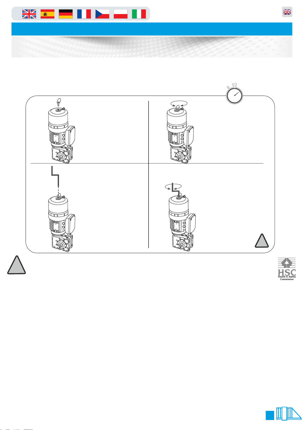
Remove the release key
from holder on the door
then insert the release
key in the exposed hole.
3. 4.
Now the Key is inserted fully
into the top hole turn
clockwise to open and anti-
clockwise to close. After this
you must remove the brake
key and replace the bung.
FAILURE TO DO THIS WILL
ALLOW DAMAGE THE
BRAKE/MOTOR AND THE
GEARBOX. !!!!!! THIS IS VERY
IMPORTANT!!!!!!
1. 2.
Remove the dust cover plug
then get the brake release key
from its holder in the cabinet
and insert it into the top of the
motor.
Keep pushing with a
downwards pressure and
turn clockwise to screw
into the hole which will
release the brake. Do
this until you feel it is
hand tight.
10 mins
60 5
10
15
20
25
30
35
40
45
50
55
!
!
in Parking and access control equipment manufactured in the UK
Automatic Sliding Gates
Opening & Closing Positions
8
When you first turn the gate on you will need to calibrate the gate, this in laymans terms means teaching
the open and close positions. You can also follow this guide should you need to re-teach the positions in
the future.
1. Enter the menu following the guide on page 9
2. Go to make sure that this is set to value this tells the gate to auto learn new settingsP.216 2
3. Now go to and change the value to P.210 5
4. Exit the menu and the display will show C.A.L.I.
5. Press the “stop” button the dots at the bottom of the screen will now flash
6. The screen will display “e.i.e.u”
7. Using the “down” arrow move the gate to the close position double check and move to step 8 (you have
to hold the button in to move similar to deadman mode)
8. Now you are happy with the close press and HOLD the stop key for 3 seconds to save the position
9. Now the display will change to “e.i.e.o”
10. Using the “up” arrow move the gate to the open position double check and move to step 11 (you have
to hold the button in to move similar to deadman mode)
11. Now you are happy with the open press and HOLD the stop key for 3 seconds to save the position
12. The display will show this denotes that the gate wants to run backward and forward to learn the i.555
torque settings and braking distances etc. To complete the learning process just keep pressing the up
and down arrow unit the display shows when opening and when closing. The calibration ope cls
/Learning is now complete.
13. Now you must enter the menu and change back to value and save, this inhibits the gate from p.216 1
self learning and settings thus keeps the positions you have taught in.
1. 2.
4.3.
60 5
10
15
20
25
30
35
40
45
50
55
10 mins
STOP
UP ARROW
STOP BUTTON
DOWN ARROW
STOP
figure.2
P.999
figure.3
figure.1
.0.99
LED Dot
Normal State = Static
Changed State = Flashing
LED Letters
or numbers
figure.4
‘STOP’
figure.5 ‘AU’

Gate Usage
in Parking and access control equipment manufactured in the UK
Automatic Sliding Gates
9
RS485
<->
USB
Software update
TST Toolbox
Optional
Parameter update
Diagnose
Update Controller
Update WiCab
TST FSAM
Mobil Safety
(Closing)
4x Stationary Safety
(Opening and Closing)
Mobil Safety
(Opening)
8K2
8K2
There are many options to operate the gate and is dependant upon which type of access control you have connected.
However there is a standard way to operate the gate by using the key switch and the arrows on the front of the panel
Instructions are assisted by pictures below.
1. Picture shown below is the key switch (if fitted) which is located on the outside of the gate cabinet (it will always
be on the opposite side to the gate arm, also picture shows the key switch keys.
2. To move the gate using the arrow keys on the panel first make sure the screen says “-e.o-” (end position open) or
“-e.c-”(end position closed) if it does not follow the troubleshooting guide on page 11 when the screen does say “-
e.o-” or “-e.c-” follow below.
3. To make the gate move to “open” press the up arrow.
4. To make the gate move to “close” press the down arrow.
Please note that the step 4 manoeuvre will not work if there is something in the way of photocells a presence on the
loops.
1. 2.
3. 4.
Key switch
keys
This key switch is mounted on
the side of the gate
Key switch
Auto Open
IDEC
IDEC
Drawing showing the “UP”
arrow being pressed
Drawing showing the “DOWN”
arrow being pressed
STOP
UP ARROW
STOP BUTTON
DOWN ARROW
STOP STOP
-e.o-
-e.c-
Gate Usage
in Parking and access control equipment manufactured in the UK
Automatic Sliding Gates
10
1. 2.
4.3.
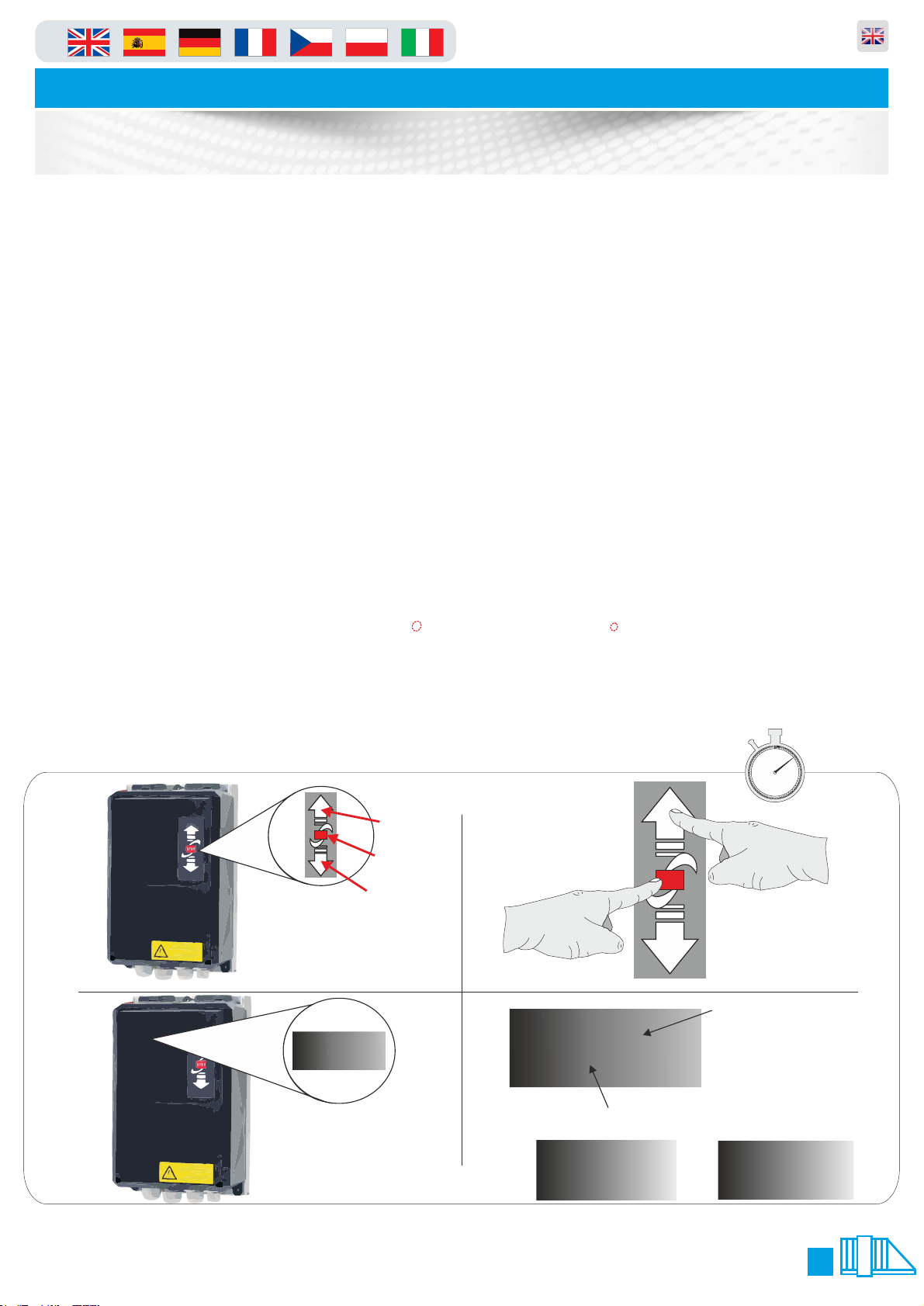
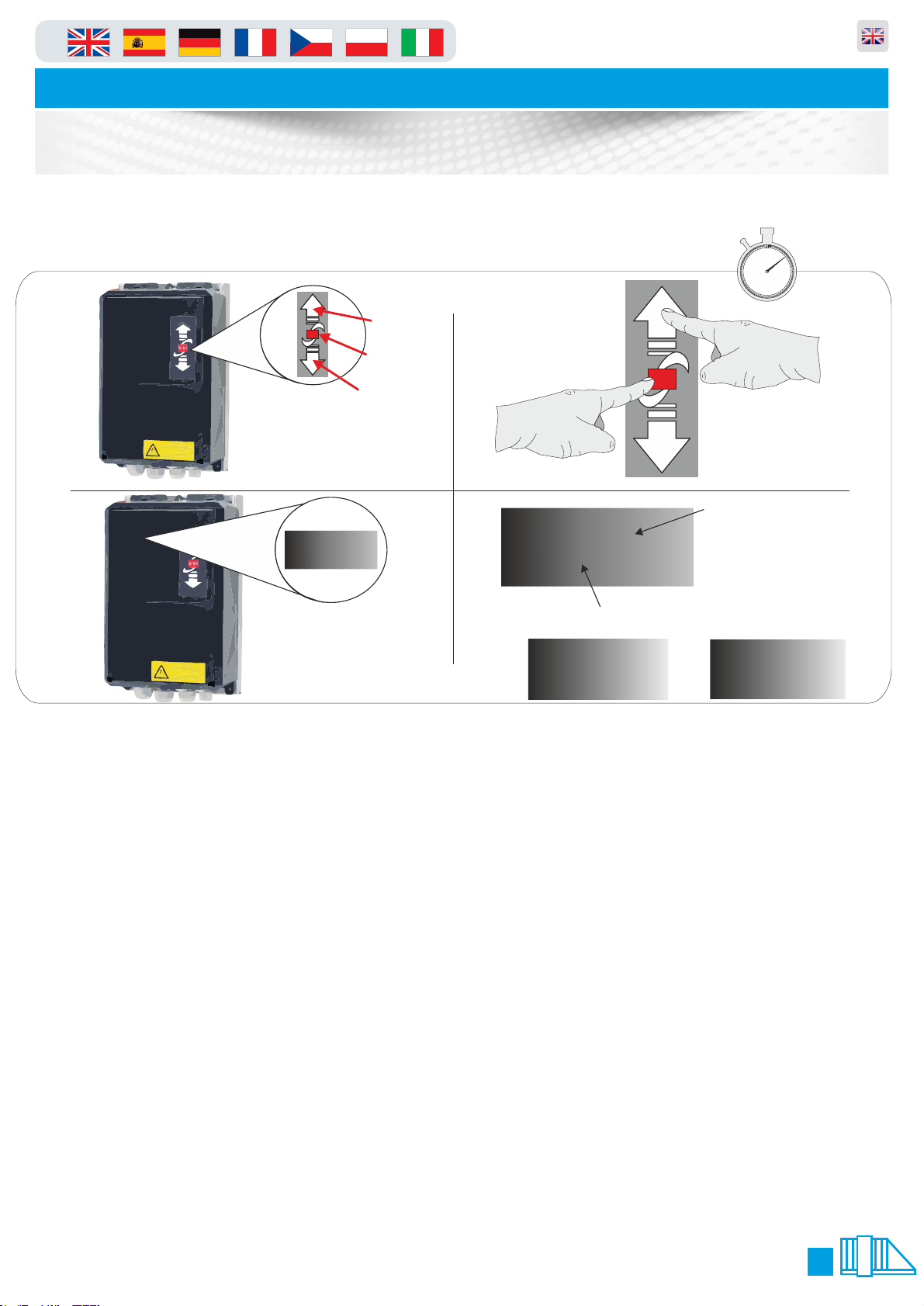
1. 1. On the front of the panel locate the function buttons (figure.1)
2. 2. Press and hold the “up” arrow and “stop” button together for 3 seconds (figure.2).
3. The LCD display and change to P.000 or P.xxx (xxx will be a parameter number last used) you are now
in programming mode and can follow the next line of instructions. When finished and to exit programming
mode press and hold the stop button for 5 seconds.
Scroll to P.999 and press the STOP button This will display “0001" change this to “0003" and press and
hold stop until the dots stop flashing under this text. Then press and release STOP button again to exit
that parameter.
4. To enter a parameter scroll using the arrow keys until the LCD display show the number you require
(figure.3) using the command buttons (figure.2). when the display shows the parameter number required
in the first column of the table below, press the STOP button for one second. You are now in that selected
parameter, should you wish to leave this parameter or discard any changes simply press the STOP button
again for 1 second ONLY!!. To make any adjustments in the selected parameter simply use the arrow keys
(figure.2) up or down, when the appropriate value is selected you should press and hold the STOP button
until the flashing dots between the value cease to flash (see figure.4). The value you selected has now
been saved to memory. To exit the menu press and hold the “stop” key for seven seconds until the LCD
display shows “STOP” or “AU” (figure.5)
60 5
10
15
20
25
30
35
40
45
50
55
10 mins
STOP
UP ARROW
STOP BUTTON
DOWN ARROW
STOP
figure.2
P.999
figure.3
figure.1
.0.99
LED Dot
Normal State = Static
Changed State = Flashing
LED Letters
or numbers
figure.4
‘STOP’
figure.5 ‘AU’
Table des matières
Autres manuels PF Clôtures et portails


