
Pegasus CCTV PDVCD-4G Manuel utilisateur

PDVCD-4G
USER MANUAL
VER.: 1.0, P/N: R040143/2

1
CONTENTS
1. SAFETY PRECAUTIONS..............................................................................................................................2
2. INTRODUCTION ...........................................................................................................................................3
3. FEATURES .....................................................................................................................................................4
4. ACCESSORIES...............................................................................................................................................5
5. INSTALLATION.............................................................................................................................................6
6. NAME and FUNCTION of EACH PART .......................................................................................................7
6.1 Front Pannel ..............................................................................................................................................7
6.2 Monitoring Mode.......................................................................................................................................9
6.3 Record Mode ...........................................................................................................................................10
6.4 Playback Mode ........................................................................................................................................ 11
7. SYSTEM SETUP ..........................................................................................................................................13
7.1 Main Menu ..............................................................................................................................................13
7.2 Date/ Time Setup .....................................................................................................................................13
7.3 Motion Detection Setup...........................................................................................................................14
7.4 Manual Record and Schedule Record Setup............................................................................................14
7.5 SD Card Options .....................................................................................................................................15
7.6 System Status...........................................................................................................................................15
7.7 Factory Default........................................................................................................................................16
8. TROUBLE SHOOTING................................................................................................................................17
9. SPECIFICATIONS........................................................................................................................................18
The author assumes no responsibility for any errors or omissions that may appear in this
document nor does he make a commitment to update the information herein.

2
CAUTION
RISK OF ELECTRIC SHOCK.
DO NOT OPEN!
CAUTION :
TO REDUCE THE RISK OF ELECTRICAL SHOCK,
DO NOT OPEN COVERS (OR BACK).
NO USER SERVICEABLE PARTS INSIDE.
REFER SERVICING TO QUALIFIED
SERVICE PERSONNEL.
1. SAFETY PRECAUTIONS
WARNING: This symbol is intended to alert the user to the presence of un-insulated “dangerous voltage”.
CAUTION: This symbol is intended to alert the user to presence of important operating and
maintenance (Servicing) instructions in the literature accompanying the appliance.
Disposal of Old Electri cal & Electronic Equipment (Applicable in the European
Union and other European countries with separate collection systems).
This symbol on the product or on its packaging indicates that this product shall not be treated as
household waste. Instead it shall be handed over to the applicable collection point for the recycling of
electrical and electronic equipment. By ensuring this product is disposed of correctly, you will help
prevent potential negative consequences for the environment and human health, which could
otherwise be caused by inappropriate waste handling of this product. The recycling of materials will
help to conserve natural resources. For more detailed information about recycling of this product,
please contact your local city office, your household waste disposal service or the shop where you
purchased the product.
The power cord is the main power connection. Therefore, constantly plug and
unplug of the power cord might result in malfunction of the product.
Do not install the product in an environment where the humidity is high.
Unless the product is waterproof or weatherproof, otherwise it can cause the image
quality to be poor.
Do not drop the product or subject them to physical shocks.
Except for vandal-proof or shockproof product, otherwise it will result malfunctions to
occur.
Never keep the product to direct strong light.
It can damage the product.
Do not spill liquid of any kind on the product.
If it gets wet, wipe it dry immediately. Alcohol or beverage can contain minerals that
corrode the electronic components.
It is advised to read the Safety Precaution Guide through carefully before operating the product,
prevent any possible danger.

3
2. INTRODUCTION
This product is a professional, personal proof collector and a movable device.
Built-in high quality pinhole camera, which enables 3 types of schedule record mode:
Manual, Continuous, and Motion Detection. Enables picture storage to built-in Flash
Memory. Furnished with fixed bracket that makes it perfect for simple installation under
many different occasions:
zApplications using the bracket, such as front door, room door, garage door and
so on.
zApplications without using bracket, such as a glass cabinet, on the table, inside
the car and so on.
Power supported by 4 AA batteries or plug-in power adaptor (DC12V). It is suggested to
use the plug-in adaptor for usage under long extended period of time or use 4 AA
batteries under short period of time, and when there is no power socket. The LED
indicator allows the user to easily distinguish the current battery status (LED indicator lit,
indicates that the power is sufficient and when the LED indicator unlit, indicates that
there are insufficient power).
Simple user-friendly interface enables easy recording setups (Record Mode, Record
Frames per Second, Motion Detection Sensitivity, and etc.). For more details, please refer
to the section on “Operation Description” and “Function Setup Description”.

4
3. FEATURES
zThe device is extremely portable with built-in Hi-resolution camera.
zSimultaneous monitoring and recording.
zAutomatic image control functions.
zFunctions supported: Auto Electronic shutter (AES), Auto White Balance (AWB),
and Auto Gain Control (AGC).
zVideo capture device record images in built-in Flash memory (capacity differs
depending model type).
zVideo capture device records images in built-in flash memory (capacity differs
depending on model type). Recording auto resumes after power loss and back.
zSupports three recording modes: Manual, Schedule Continuous, and Schedule
Motion Detection.
zSupports both NTSC and PAL system.
zTwo types of resolution (selectable): 320x240 and 640x480.
zSelectable compression image qualities and frame rate.
zMotion detection with adjustable sensitivity level.
zSupports flexible playback mode: Normal Playback, Rewind, Fast Forward, and
Step Playback.
zSupports DC12V or 4xAA batteries (use anywhere, camera can be powered by
battery, so power outlet is unnecessary).

5
4. ACCESSORIES
Unpack the product and inspect to make sure that nothing noticeable is wrong or that all
accessories are included inside the product package. If you have any questions, please
contact your local dealer.
Item Description Item Picture Qty.
Camera
1
Video Line
2
Power Adaptor
1
Manual
1
Bracket
1

6
5. INSTALLATION
Please refer to the instructions below for camera mounting and bracket installation:
zBracket Installation Guide:
zCamera Mounting Installation Guide:
zVideo Output and Power Adaptor Connection Guide:

7
6. NAME and FUNCTION of EACH PART
6.1 Front Pannel
(1) Function Switch
zNTSC<->PAL
The two most common video standards used are NTSC and PAL. NTSC is
the video system or standard commonly used in North America, Taiwan,
Japan, Korea, and South America. PAL is the predominant video system or
standard mostly used in China, Hong Kong, Europe, and India.
Please select and switch to the system that best suits your location. Take
note that this setup is only effective when it is setup before power-on.
zFull Stop<->Overwrite
Select whether to overwrite the recorded memories or to stop recording
when memory is full. One may select “Overwrite”, the memory will be
overwritten starting with the oldest data first.
Selecting “Full Stop”, when the memory system is full, it switches from
record mode to stop mode, and the LED indicator on the front panel will
start flashing. Take note that this setup is only effective when it is setup
before power-on.
(2) Video Output Jack
To enable monitoring functions, connect one terminal to the video out jack and
the other terminal to the monitor (TV).
(3) Po wer Switch
Select “On” to switch on the device, and “Off” to switch off the device.
8
When power-loss occurs during recording, error may occur. To switch off the
power correctly, please refer to “6.3 Record Mode”.
(4) Power Source Jack.
(5) LED Operation Mode Indicators
LED light easily allows the user to distinguish the current system status. For
example REC LED: The LED indicator lit indicates recording, and when unlit
indicates no recording (REC LED flashes when the power supply is
insufficient).
(6) Button
Buttons commonly used: Rec/ . But all other 5 buttons are applied during
setups. Every button under each mode has different definition. For more details,
please refer to the section on “Function Description Table”.
(7) LED Power Indicator
The LED indicator lit indicates that the device is powered up and when unlit
indicates that the power is insufficient or switched off.
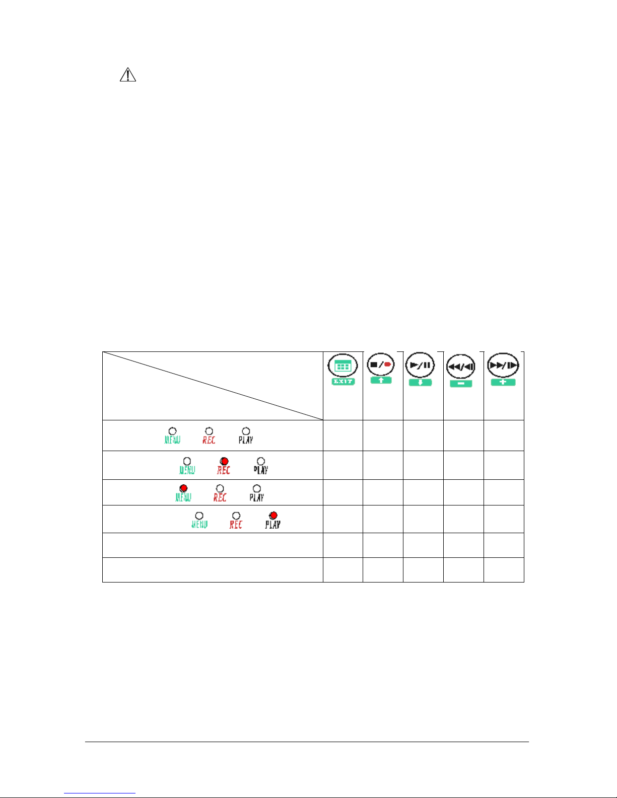
Function Description Table
BUTTON
MODE
STOP MODE
Switch to Menu
Setup Mode
Switch to
Record Mode
Switch to
Playback Mode
RECORD MODE Switch to
Stop Mode
MENU MODE
Refer to Setup
Description
Refer to Setup
Description
Refer to Setup
Description Refer to Setup
Description Refer to Setup
Description
PLAYBACK MODE
FREEZE MODE Switch to
Stop Mode
Continuous
Playback Step
Rewind Step
Forward
CONTINUOUS MODE Switch to
Stop Mode
Pause
Playback Fast
Rewind Fast
Forward
Please read the “Function Description Table” carefully before operation, to enable quick
understanding of the relations between the button and mode.
The LED indictor (on the front panel) represents the current mode or screen display status.
Under different mode each function has different meanings. The Function Description
Tabl e clearly lists the LED light as it appears during different mode and its corresponding
relations with the function buttons. The system is mainly divided into stop mode, record
mode, playback mode, setup menu mode, and etc. These modes will be discussed on the
later section.

9
Power On
1. The power switch is situated on the right side of the device.
NOTE: Each time after power-on, the system auto-detects its peripherals. When the REC LED
flashes indicate that the system memory is proceeding testing (complete boot time is several
seconds). When an image file error has been detected, the system will initiate auto repair.
2. After power on, the system auto enters live monitoring. When the system is
currently under schedule recording, it auto enters record mode.
3. “” icon shown on the status line, indicates that the system memory is operating
normally.
4. When problem occurs to the system memory. Press record or playback, the
corresponding LED indicator will not lit. Play, Menu, and Rec indicator will flash
quickly. Please re-format before proceeding.
5. When system memory is writing data during recording, record indicator will flash
slowly.
6. After power-loss the system auto returns to the previous recording mode.
6.2 Monitoring Mode
1 The monitoring mode is displayed according to the pre-setup (system setup after
power-on), and the user may view live monitoring.
cTime Display: System Date and Time.
dRecord Status Display: Manual Record Parameter.
:Record Resolution, please refer to【7.4 Record Setup】for VIDEO SIZE setup.
:Record Quality, please refer to【7.4 Record Setup】for VIDEO QUALITY setup.
3 System Memory Status:
:Malfunction.
:Proceeding file testing.
:Functioning normally.
C:Continuous record.
1
2
3
2004 /02 /01 08:10:0 3
Table des matières
Manuels Système de sécurité populaires d'autres marques


EDM
EDM Solution 6+6 Wireless-AE Manuel utilisateur

Highway Safety Group
Highway Safety Group EA401 Manuel utilisateur

Siren
Siren LED GSM Manuel utilisateur

Detection Systems
Detection Systems 7090i Instructions de montage

Se-Kure Controls
Se-Kure Controls MicroMini SK-4841 Manuel utilisateur

Siemens
Siemens FDM273 Manuel utilisateur