peerless-AV SC560FK Mode d’emploi

Installation and Assembly:
32" - 65" (81 - 165 cm) Kiosk Cart
Models: SC560FK
ISSUED: 09-30-11 SHEET #: 009-9057-3 05-23-12
2300 White Oak Circle • Aurora, Il 60502 • (800) 865-2112 • Fax: (800) 359-6500 • www.peerlessmounts.com
Max UL Load Capacity:
150 lb (68 kg) display
15 lb (6.8 kg) component

2 of 11 ISSUED: 09-30-11 SHEET #: 009-9057-3 05-23-12
NOTE: Read entire instruction sheet before you start installation and assembly.
Table of Contents
Parts List............................................................................................................................................................................ 3, 4
Assembling Cart.....................................................................................................................................................................5
Installing Adapter Brackets to Flat Panel Display...................................................................................................................8
Mounting Flat Panel Display................................................................................................................................................ 10
Cable Management............................................................................................................................................................. 10
Tools Needed for Assembly
• phillips screwdriver
• Do not begin to install your Peerless product until you have read and understood the instructions and warnings
contained in this Installation Sheet. If you have any questions regarding any of the instructions or warnings, for US
customers please call Peerless customer care at 1-800-865-2112, for all international customers, please contact
your local distributor.
• This product should only be installed by someone of good mechanical aptitude, and fully understands these
instructions.
• Never exceed the Maximum UL Load Capacity on page 1.
• Always use an assistant or mechanical lifting equipment to safely lift and position equipment.
• Tighten screws firmly, but do not overtighten. Overtightening can damage the items, greatly reducing their holding
power.
• The cart is not affixed or secured to the floor, and may therefore tip over and/or fall if display and/or cart is shaken
or hit. Always monitor children and do not let children play alone around cart as they could get hurt by a falling
display. Not recommended for use in areas with heavy traffic.
• This product is intended for indoor use only. Use of this product outdoors could lead to product failure and personal
injury.
WARNING

3 of 11 ISSUED: 09-30-11 SHEET #: 009-9057-3 05-23-12
Before you begin, make sure all parts shown are included with your product.
Parts List
Description Qty. Part Number
A
base 1 009-1223
Bcolumn 1 009-1427
Ccolumn bracket 1 009-1424
Dtilt plate 1 009-1423
Eadapter plate 1 201-1110
Fadapter bracket 2 201-1510
G3/8-16 x 1" button socket cap screw 3 520-1354
H3/8-16 x 1-1/2" button socket cap screw 4 520-1329
I5/16-18 x 3/8" button socket cap screw 4 520-1693
JM10 lock washer 3 540-9424
KM10 x 15 mm button socket cap screw 4 520-9262
L3/8-16 X 2-1/2" button socket cap screw 3 520-9550
M6 mm allen wrench 1 560-9716
N7/32" allen wrench 1 560-9715
Oright leg 1 009-1295
Pleft leg 1 009-1296
Qcaster 2 600-0044
Rcaster with brake 2 600-0045
Sjoint connector 4 530-1037
T3/16" allen wrench 1 560-0071
Utop plate 1 201-1724
V
bottom plate 1 201-1699
Wrubber feet (pack of four) 1 570-1036
X
M8 x 15mm socket pin screw 4 520-1068
Y
M10 x 15mm penta-pin screw 4 520-9263
ZM10 penta-pin tool 1 520-9260
AA 4mm allen wrench 1 560-9646
Parts may appear slightly different than illustrated.
B
C
D
H
LJ
KI
F
M
T
N
E
A
P
O
SR
Q
G

4 of 11 ISSUED: 09-30-11 SHEET #: 009-9057-3 05-23-12
UVWXY
ZAA
M5 x 25mm (4)
(520-1122)
M5 x 12mm (4)
(520-1064) M6 x 12mm (4)
(520-1050)
M6 x 25mm (4)
(520-1211) M8 x 25mm (4)
(520-1101)
M8 x 12mm (4)
(520-1724) .75" spacer (4)
(540-1059)
Multi-washer (4)
(580-1398)
Security Adapter Bracket Fasteners

5 of 11 ISSUED: 09-30-11 SHEET #: 009-9057-3 05-23-12
Insert right leg (O) into base (A) as shown in figure 1.1. Then line up holes of right leg with holes in base. Fasten
right leg to base using two 3/8-16 x 1-1/2" button socket cap screws (H) and two joint connectors (S), tighten using
3/16"allen wrench (T) and 7/32"allen wrench (N) as shown in figure 1.2.
NOTE: Left and right legs can be identified by looking at the cart from the front.
Repeat for left side of column base with left leg (P).
1
O
S
H
fig. 1.2
fig. 1.1
AO
FRONT OF CART
FRONT OF LEG
2Insert casters (Q, R) into holes of support legs (O, P) and hand thread to secure. Attach casters with brake (R)to
rear of support legs (O, P). Attach casters without brake (Q)to front of support legs (O, P) as shown.
NOTE: Lock brakes on casters to restrict movement during installation.
P
R
Q
O
HAND THREAD
HOLD WHEEL

6 of 11 ISSUED: 09-30-11 SHEET #: 009-9057-3 05-23-12
Attach column (B) to base (A) with three
3/8-16 x 2-1/2" button socket cap screws (L) and
three M10 lock washers (J). Tighten screws using
7/32" allen wrench (N).
Attach tilt plate (D) to bottom plate (V) with four
M10 x 15 mm button socket cap screws (K).
Tighten screws using 6 mm allen wrench (M).
Attach the column bracket (C) to column (B) with
three 3/8-16 x 1" button socket cap screws (G).
Tighten screws using 7/32" allen wrench (N).
Attach tilt plate (D) to column bracket (C) with four
5/16-18 x 3/8" button socket cap screws (I) as
shown in rear view.
Tilt can be adjusted to 0° or 30°.
3
5
4
6
REAR VIEW
D
K
D
V
C
C
I
G
B
A
LJ
B

7 of 11 ISSUED: 09-30-11 SHEET #: 009-9057-3 05-23-12
Attach top plate (U) to adapter plate (E) with four
M10 x 15 mm penta-pin screws (Y).
Tighten screws using penta-pin tool (Z).
Secure four rubber feet (W) to bottom of CPU as
shown below.
Secure CPU to top plate (U) using safety belt.
NOTE: Safety belt may need to be loosened to
attach CPU to component box top plate.
Secure top plate (U) to bottom plate (V) with four M8
x 15 mm screws (X) as shown in rear view. Tighten
screws using 4 mm allen wrench (AA).
7 8
9
REAR VIEW
E
ZW
U
U
X V
U
CPU
CPU
SAFETY BELT
CPU MAYAPPEAR
DIFFERENT THAN
ILLUSTRATED
8-1

8 of 11 ISSUED: 09-30-11 SHEET #: 009-9057-3 05-23-12
NOTE: "X" dimensions should be equal.
Installing Adapter Brackets to Flat Panel Display
To prevent scratching the display, set a cloth on a flat, level surface that will support the weight of the display. Place
display face side down. Refer to display manufacturers instructions or customer service, for removing any knobs,
base, cover, or screw(s) on the back of the display to prepare mounting. These need to be removed to allow the
adapter brackets (F) to be attached. Select the small, medium, large or extra large screws from the baffled fastener
pack then attach adapter brackets to display following figure 10.1 or 10.2.
NOTE: Top and bottom mounting holes must be used for attaching adapter brackets. Verify that all holes are
properly aligned, and then tighten screws using 4 mm security allen wrench (AA).
FCENTER BRACKETS
VERTICALLY ON BACK
OF DISPLAY
X
X
10
Notes:
• The number of fasteners used will vary,
depending upon the type of display.
• Multi-washers and spacers may not be
used, depending upon the type of display.
• Use the corresponding hole in the multi-
washer that matches your screw size as
shown.
MEDIUM HOLE FOR M5 SCREWS
SMALL HOLE FOR M4 SCREWS
LARGE HOLE FOR M6 SCREWS
MULTI-WASHER
NOTE: For flat back displays proceed to step 10-1. For bump-out or recessed back display skip to step 10-2
• Tighten screws so adapter brackets are firmly attached. Do not tighten with excessive force. Overtightening can
cause stress damage to screws, greatly reducing their holding power and possibly causing screw heads to become
detached. Tighten to 40 in. • lb (4.5 N.M.) maximum torque.
• If screws don't get three complete turns in the display inserts or if screws bottom out and adapter brackets are still
not tightly secured, damage may oXur to display or product may fail.
WARNING

9 of 11 ISSUED: 09-30-11 SHEET #: 009-9057-3 05-23-12
Begin with the shortest length screw, hand thread through multi-washer and adapter bracket into display as
shown below. Screw must make at least three full turns into the mounting hole and fit snug into place. Do not
over tighten. If screw cannot make three full turns into the display, select a longer length screw from the baffled
fastener pack. Repeat for remaining mounting holes, level brackets and tighten screws.
NOTE: Spacers may not be used, depending upon the type of display.
Begin with longer length screw, hand thread through multi-washer, adapter bracket and spacer in that order into
display as shown below. Screw must make at least three full turns into the mounting hole and fit snug into place.
Do not over tighten. If screw cannot make three full turns into the display, select a longer length screw from the
baffled fastener pack. Repeat for remaining mounting holes, level brackets and tighten screws.
For Flat Back Display
For Bump-out or Recessed Back Display
10-1
10-2
If you have any questions, please call Peerless customer care at 1-800-865-2112.
If you have any questions, please call Peerless customer care at 1-800-865-2112.
DISPLAY
MULTI-WASHER
SCREW
ADAPTER
BRACKET (F)
fig. 10.2
SPACER
ADAPTER
BRACKET (F)
DISPLAY
fig. 10.1
MULTI-WASHER
SCREW
10 of 11 ISSUED: 09-30-11 SHEET #: 009-9057-3 05-23-12
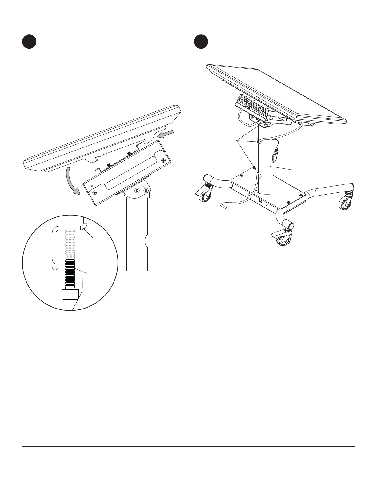
Mounting Flat Panel Display
Hook adapter brackets (F) onto adapter plate (E).
Then slowly swing display down as shown. Turn
safety/security screws, using 4 mm security allen
wrench (AA), clockwise at least six times to prevent
display from being removed as shown in detail 1 of
figure 11.1.
NOTE: To lock the display down, tighten security
screws to adapter plate (E) as shown in detail 1.
11
Cable Management
Run cables through column (B) using cable
management holes.
© 2012, Peerless Industries, Inc. All rights reserved.
All other brand and product names are trademarks or registered trademarks of their respective owners.
Peerless Industries, Inc.
2300 White Oak Circle
Aurora, Il 60502
www.peerlessmounts.com
fig 11.1
DETAIL 1
E
SECURITY
SCREWS
CABLE
MANAGEMENT
HOLES
F
B
12
Table des matières
Autres manuels peerless-AV Chariot d'extérieur

peerless-AV
peerless-AV SC551GL Mode d’emploi

peerless-AV
peerless-AV SC550 Mode d’emploi

peerless-AV
peerless-AV SC590 Mode d’emploi

peerless-AV
peerless-AV SC550GL Mode d’emploi

peerless-AV
peerless-AV SR598 Manuel utilisateur

peerless-AV
peerless-AV Mobile Videowall Trolley PDVWM 2x2 46 55 L Manuel utilisateur

peerless-AV
peerless-AV DS-C560-1X3 Manuel utilisateur

peerless-AV
peerless-AV DS-C555-4X2 Manuel utilisateur

peerless-AV
peerless-AV DS-C555-3X2 Manuel utilisateur


