Peavey MM 8830 Manuel utilisateur
MM™8800 Series
MM™8830
MM™8840
MM™8848
Operating Guide
Architectural Acoustics®
2
Intended to alert the user to the presence of uninsulated "dangerous voltage" within the product's enclosure
that may be of sufficient magnitude to constitute a risk of electric shock to persons.
Intended to alert the user of the presence of important operating and maintenance (servicing) instructions in the
literature accompanying the product.
CAUTION: Risk of electrical shock – DO NOT OPEN!
CAUTION: To reduce the risk of electric shock, do not remove cover. No user serviceable parts inside. Refer servicing to
qualified service personnel.
WARNING: To prevent electrical shock or fire hazard, do not expose this appliance to rain or moisture. Before using this
appliance, read the operating guide for further warnings.
Este símbolo tiene el propósito de alertar al usuario de la presencia de "(voltaje) peligroso" que no tiene
aislamiento dentro de la caja del producto que puede tener una magnitud suficiente como para constituir riesgo de
corrientazo.
Este símbolo tiene el propósito de alertar al usario de la presencia de instruccones importantes sobre la operación
y mantenimiento en la literatura que viene con el producto.
PRECAUCION: Riesgo de corrientazo – No abra.
PRECAUCION: Para disminuír el riesgo de corrientazo, no abra la cubierta. No hay piezas adentro que el usario pueda
reparar. Deje todo mantenimiento a los técnicos calificados.
ADVERTENCIA: Para evitar corrientazos o peligro de incendio, no deje expuesto a la lluvia o humedad este aparato
Antes de usar este aparato, lea más advertencias en la guía de operación.
Ce symbole est utilisé pur indiquer à l'utilisateur la présence à l'intérieur de ce produit de tension non-isolée
dangereuse pouvant être d'intensité suffisante pour constituer un risque de choc électrique.
Ce symbole est utilisé pour indiquer à l'utilisateur qu'il ou qu'elle trouvera d'importantes instructions sur
l'utilisation et l'entretien (service) de l'appareil dans la littérature accompagnant le produit.
ATTENTION: Risques de choc électrique – NE PAS OUVRIR!
ATTENTION: Afin de réduire le risque de choc électrique, ne pas enlever le couvercle. Il ne se trouve à l'intérieur
aucune pièce pouvant être réparée par l'utilisateur. Confier l'entretien à un personnel qualifié.
AVERTISSEMENT: Afin de prévenir les risques de décharge électrique ou de feu, n'exposez pas cet appareil à la pluie
ou à l'humidité. Avant d'utiliser cet appareil, lisez les avertissements supplémentaires situés dans le guide.
Dieses Symbol soll den Anwender vor unisolierten gefährlichen Spannungen innerhalb des Gehäuses warnen, die
von Ausreichender Stärke sind, um einen elektrischen Schlag verursachen zu können.
Dieses Symbol soll den Benutzer auf wichtige Instruktionen in der Bedienungsanleitung aufmerksam machen, die
Handhabung und Wartung des Produkts betreffen.
VORSICHT: Risiko – Elektrischer Schlag! Nicht öffnen!
VORSICHT: Um das Risiko eines elektrischen Schlages zu vermeiden, nicht die Abdeckung enfernen. Es befinden sich
keine Teile darin, die vom Anwender repariert werden könnten. Reparaturen nur von qualifiziertem Fachpersonal
durchführen lassen.
ACHTUNG: Um einen elektrischen Schlag oder Feuergefahr zu vermeiden, sollte dieses Gerät nicht dem Regen oder
Feuchtigkeit ausgesetzt werden. Vor Inbetriebnahme unbedingt die Bedienungsanleitung lesen.
3
E N G L I S H
E N G L I S H
MediaMatrix®
1
BoB Interface Features
• Eight balanced audio inputs and eight balanced audio outputs, each utilizing
18-bitconverterstotransferaudiodatatoandfromtheMediaMatrixsystem.
• Eight analog control inputs that may be used to control a device in a
MediaMatrix view.
•Eightdigitalcontroloutputs that may be used todriveexternalTTLlogiclevel
devices.
• A digital interface, 9-pin D-type connector.
The MediaMatrix®MM-8800 series Break-Out-Box (BoB) provides the means of interconnection between the
MediaMatrix MainFrame, MiniFrame or X-Frame, and other components of the audio system.
FRONT PANEL
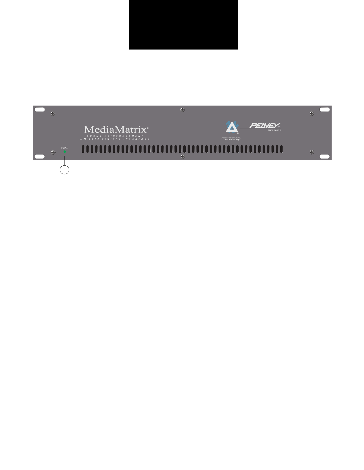
POWER LED (1)
Illuminates when AC power is being supplied to the unit.
4
2
REAR PANEL
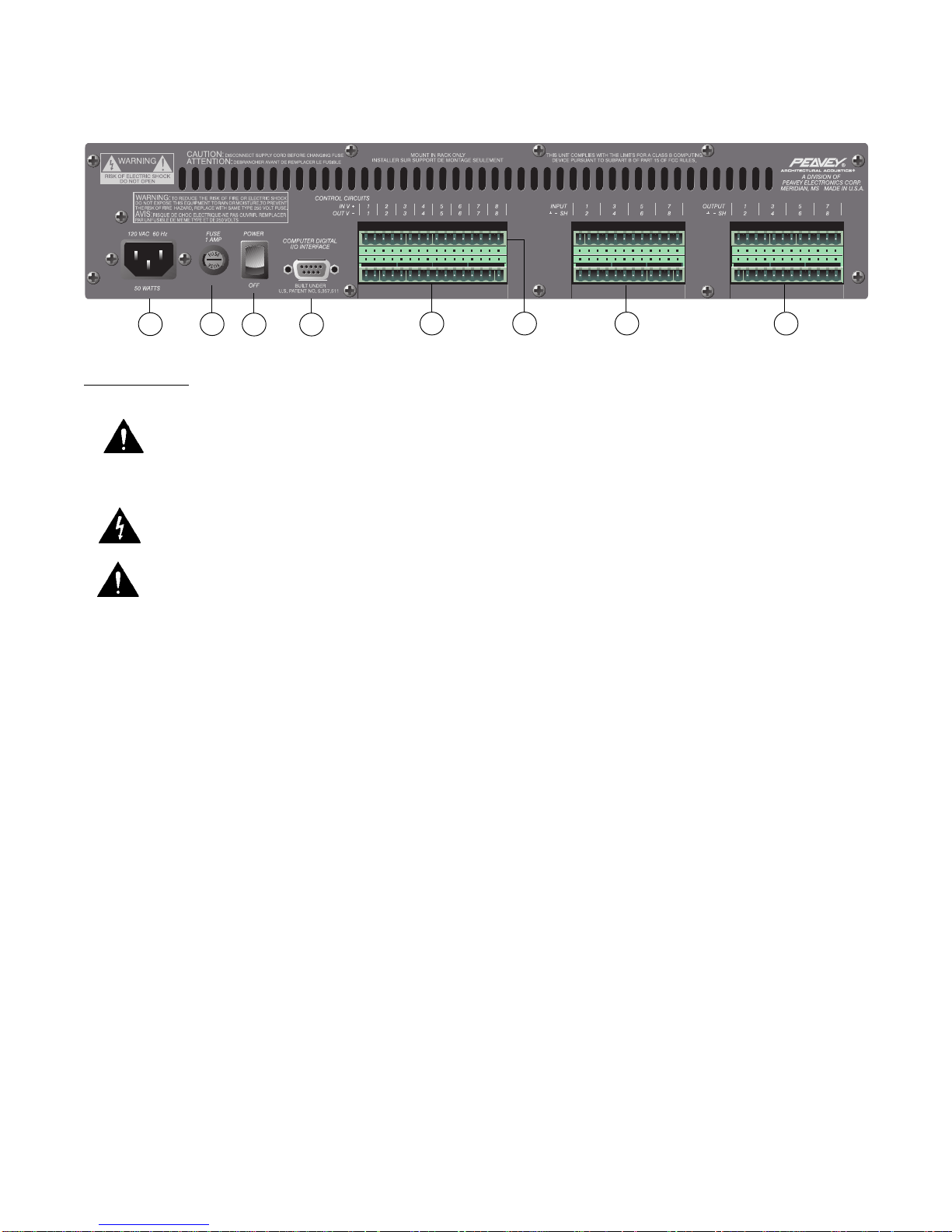
IEC LINE CORD INPUT (2)
Provided to accept the removable AC line cord.
FUSE (3) WARNING: THE FUSE SHOULD ONLY BE REPLACED WHEN THE POWER CORD HAS BEEN
DISCONNECTED FROM ITS POWER SOURCE.
CAUTION: USING A FUSE LARGER THAN THE RECOMMENDED SIZE COULD RESULT IN
PERMANENT DAMAGE TO THE UNIT.
The fuse is located within the cap of the fuseholder. If the fuse should fail, IT MUST BE REPLACED
WITH THE SAMETYPEAND VALUE IN ORDER TOAVOID DAMAGETO THE EQUIPMENTAND
TO PREVENTVOIDING THE WARRANTY. If the unit repeatedly blows fuses, it should be taken to
a qualified service center for repair.
POWER SWITCH (4)
Switch to “On” position to turn on. The red LED will illuminate indicating power is being supplied to the unit.
COMPUTER DIGITAL I/O INTERFACE (5)
Connect the 9-pin D-type BoB cable here. This cable provides the link to the MediaMatrix system.
CONTROL CIRCUIT OUTPUTS (6)
These are TTL level outputs, switchable from within a MediaMatrix view. There are two electrical connections
per channel; the right connection is the ground interface and the left connection is the TTLlevel output. See the
Wiring Connections
section for Control Output circuit examples.
CONTROL CIRCUIT INPUTS (7)
The inputs provide the means of controlling a device within a MediaMatrix view. There are two electrical
connections per channel. See the
Wiring Connections
section for Control Input circuit examples.
AUDIO INPUTS (8)
Each of these eight channels is a balanced analog audio input to the MediaMatrix system. See the
Wiring
Connections
section for Audio Input wiring examples.
AUDIO OUTPUTS (9)
Each of these eight channels is a balanced analog audio output from the MediaMatrix system. See the
Wiring
Connections
section for Audio Output wiring examples.
Rear Panel:
34 5 89
6 7

5
SPECIFICATIONS
Due to our efforts for constant improvements,
features and specifications listed herein are subject to change without notice.
TM
®
SYSTEM SPECIFICATIONS
Maximum Input Level:
+18 dBu or +24 dBu
Input Impedance:
Greater than 12K ohms for +18 dBu full scale
Greater than 15K ohms for +24 dBu full scale
Electronically Balanced
Maximum Output Level:
+16 dBu, +12 dBu, +18 dBu, or +24 dBu
(600 ohm load)
Output Impedance:
200 ohms, electronically balanced
Power Requirements:
Domestic: 120V AC, 60 Hz, 50W
Export: 230V AC, 50/60 Hz, 50W
Dimensions & Weight:
3.5" H x 19" W x 11.25" D (excluding connectors)
17 lbs.
Included Accessories:
IEC Line Cord
6' BoB Cable
(2) 16-position Phoenix-type connectors
(4) 12-position Phoenix-type connectors
ANALOG TO DIGITAL CONVERTER
MM-8830: 18-bit, 64x oversampled, 32 kHz sample rate
MM-8840: 18-bit, 64x oversampled, 44.1 kHz sample rate
MM-8848: 18-bit, 64x oversampled, 48 kHz sample rate
Frequency Response:
MM-8830: ±1.0 dB, 20 Hz to 16 kHz
MM-8840: ±0.5 dB, 20 Hz to 20 kHz
MM-8848: ±0.5 dB, 20 Hz to 20 kHz
Signal-to-Noise Ratio:
MM-8830: Greater than 96 dB
MM-8840: Greater than 98 dB
MM-8848: Greater than 100 dB
Crosstalk:
MM-8830: Greater than 95 dB
MM-8840: Greater than 95 dB
MM-8848: Greater than 97 dB
Total Harmonic Distortion:
MM-8830: Less than 0.01% at 1 kHz
MM-8840: Less than 0.01% at 1 kHz
MM-8848: Less than 0.01% at 1 kHz
DIGITAL TO ANALOG CONVERTER
MM-8830: 18-bit, 64x oversampled, 32 kHz sample rate
MM-8840: 18-bit, 64x oversampled, 44.1 kHz sample rate
MM-8848: 18-bit, 64x oversampled, 48 kHz sample rate
Frequency Response:
MM-8830: ±1.0 dB, 20 Hz to 16 kHz
MM-8840: ±0.5 dB, 20 Hz to 20 kHz
MM-8848: ±0.5 dB, 20 Hz to 20 kHz
Signal-to-Noise Ratio:
MM-8830: Greater than 92 dB
MM-8840: Greater than 95 dB
MM-8848: Greater than 96 dB
Crosstalk:
MM-8830: Greater than 91 dB
MM-8840: Greater than 94 dB
MM-8848: Greater than 95 dB
Total Harmonic Distortion:
MM-8830: Less than 0.01% at 1 kHz
MM-8840: Less than 0.01% at 1 kHz
MM-8848: Less than 0.01% at 1 kHz
6
Wiring Diagram
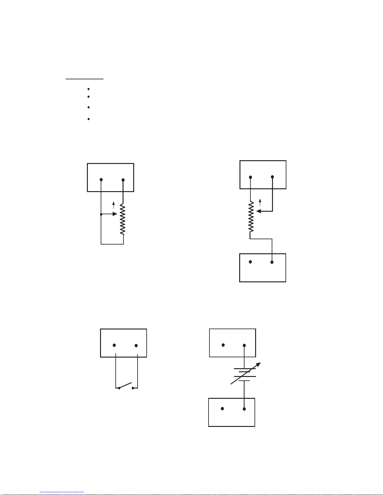
Control Input Examples
Input Sources:
3. Variable DC supply can be used to control device - NO MORE THAN 10V!
2. Switch allows binary control of a device in a MediaMatrix view.
1. Linear example allows control of device by tracking pot linearly.
Nonlinear example allows control of device by tracking pot nonlinearly.
(3) DC Supply
+
In
V
–
Out
V
Ø-1Ø V DC
(2) Switch
+
In
V
(1) Linear Example
+
In
V
CW
10K Linear Pot
(1) Nonlinear Example
CW
10K Linear Pot
–
Out
V
+
In
V
7
Wiring Diagram
Control Output Examples
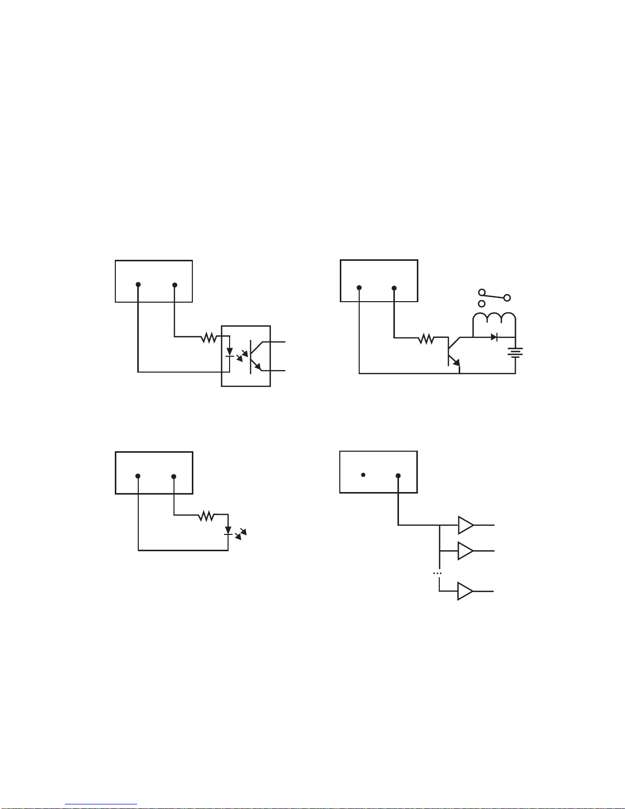
The eight control outputs appear on a separate Phoenix connector
on the back of the Break-Out-Box. They provide logic outputs from
the system. The output voltage is TTL format. Outputs are capable
of sourcing 6ma and sinking 20ma while maintaining valid TTL levels.
There are two electrical connections for each channel output control.
When viewing the unit from the back, the left connection is the positive
terminal. These outputs can be used to control devices as follows:
An Opto-Isolator:
–
Out
100Ω
V
An LED:
–
Out
100Ω
V
Up to 15 TTL Loads:
–
Out
V
A Relay:
1000Ω
–
Out
V
8
Wiring Diagram
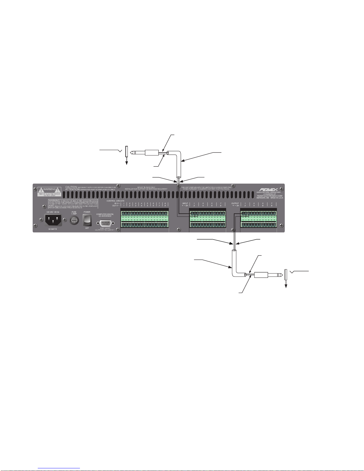
Using the Breakout Box with an Unbalanced Audio Device
OUTPUT
1/4" Phone Plug
Unbalanced Audio
Device Output
Sleeve
Sleeve (shield) Tip (insulated conductor)
Tip
(insulated conductor) Sleeve (shield)
Sleeve
Single-Conductor,
Shielded Wire
Single-Conductor,
Shielded Wire
INPUT
1/4" Phone Plug
Unbalanced Audio
Device Input
1. Unbalanced audio device output to balanced BoB input.
2. Balanced BoB output to unbalanced audio device input.
Tip (insulated conductor)
Tip (insulated conductor)
Note: Be sure to ground the unused negative terminal on the BoB input/output.
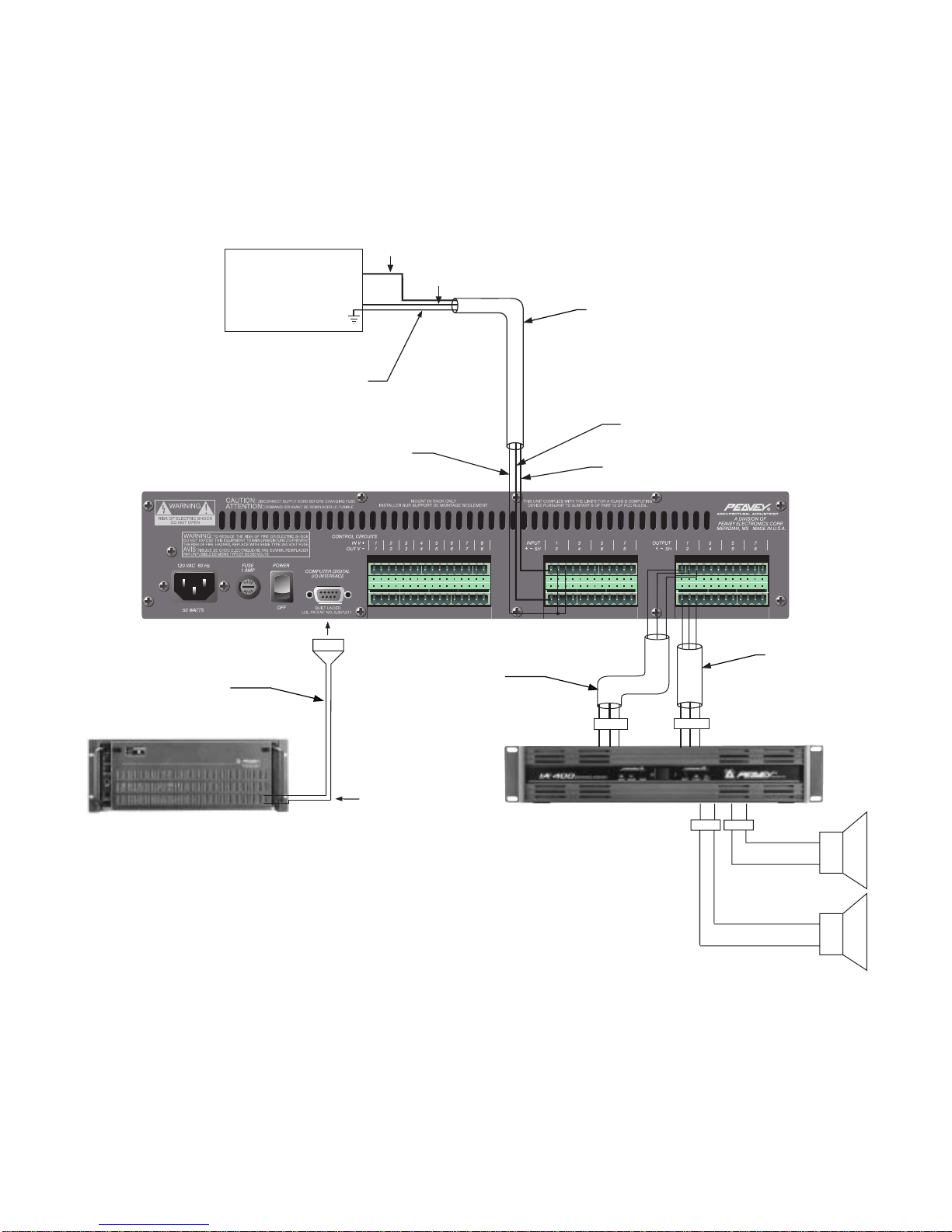
9
Left Out
Right Out
Shield
Shield
BoB Cable
BoB Cable
Connected to
MM DSP Card
MediaMatrix Computer
+ –
SH
+ –
SH
Left Input Right Input
+ -
IA 400 Power Amp
Left Out Right Out
+ -
+
–
+
–
Right (
Insulated Conductor 2)
Left (
Insulated Conductor 1)
Shielded,
2-Conductor
Wire
Shielded,
2-Conductor
Wire
Shielded,
2-Conductor
Wire
Insulated Conductor 1
Insulated Conductor 2
Note: If using an unbalanced audio source, be sure to ground the unused negative inputs on the BoB.
Wiring Diagram
CD Player or Other Line Level Audio Device
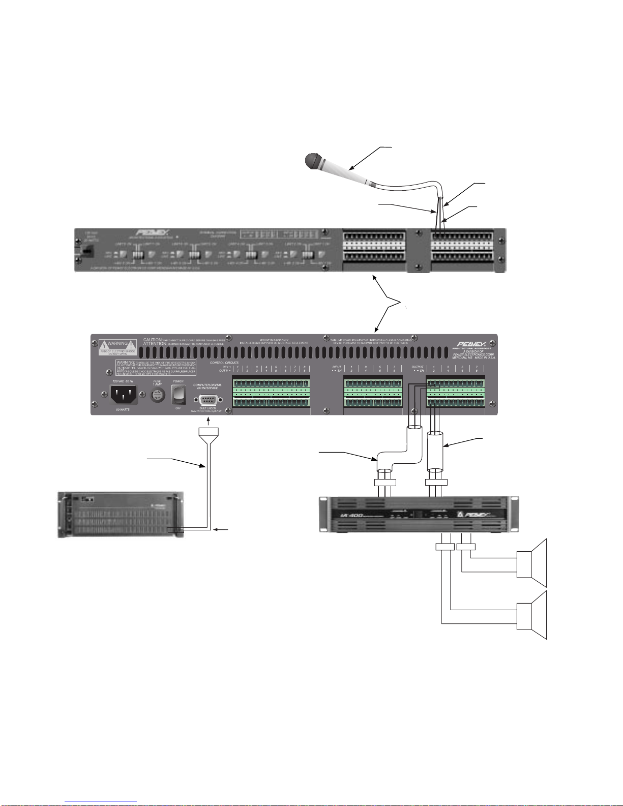
10
Wiring Diagram
MediaMatrix System with Microphone Preamp
Pin-to-Pin Connections use
Shielded, 2-Conductor Wire
per Channel (x8)
Pin 2
(+ conductor)
Pin 1 (ground)
Microphone
Pin 3 (- conductor)
+ – SH + – SH
Left Input Right Input
+ -
IA 400 Power Amp
Left Out Right Out
+ -
+
–
+
–
Shielded,
2-Conductor
Wire
Shielded,
2-Conductor
Wire
BoB Cable
BoB Cable
Connected to
MM DSP Card
MediaMatrix Computer
A/A-8P
™
MM-8800 Series BoB
Ce manuel convient aux modèles suivants
2
Table des matières
Langues :
Autres manuels Peavey Accessoires

Peavey
Peavey RADIAL X 22 Manuel utilisateur

Peavey
Peavey Spectrum Analog Filter Manuel utilisateur

Peavey
Peavey CinemAcoustics CA-S7330 Manuel utilisateur

Peavey
Peavey DPM SP Manuel utilisateur

Peavey
Peavey 4000F Manuel utilisateur

Peavey
Peavey PCS Manuel utilisateur

Peavey
Peavey MAP 8x4 Manuel utilisateur

Peavey
Peavey Model 44T Manuel utilisateur

Peavey
Peavey TLO-S Manuel utilisateur

Peavey
Peavey MPT-XC Manuel utilisateur