Peak 210C Manuel
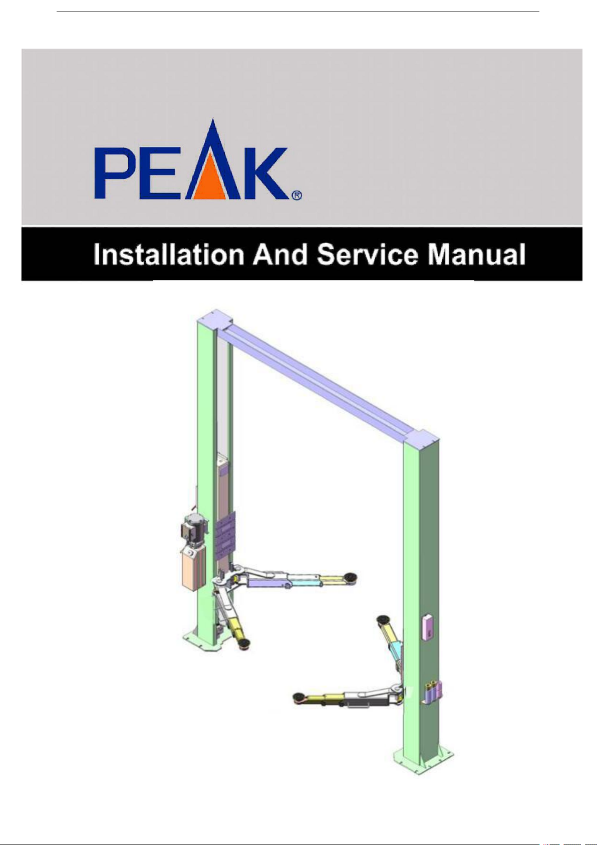
TWO-POST LIFT
Model:210C 210CX

1
CONTENTS
Product Features and Specifications ..............................................1
Installation Requirement .............................................................4
Steps of Installation ………………………………………………………..…………..........5
Exploded View ...........................................................................22
Test Run ...................................................................................25
Operation Instruction .................................................................27
Maintenance .............................................................................27
Trouble Shooting .......................................................................28
Parts List ………...........................................................................29

1
I. PRODUCT FEATURES AND SPECIFICATIONS
CLEARFLOOR DIRECT-DRIVED MODEL FEATURES
MODEL 210C (See Fig.1)
· Direct-driving design, minimize the lift wear parts and breakdown ratio.
· Dual hydraulic direct-drive cylinders, designed and made as standard, utilizing oil
seal in cylinder.
· Self-lubricating UHMW Polyethylene sliders and bronze bush.
· Single-point safety release, and dual safety design.
· Clear-floor design, provide unobstructed floor space.
· Overhead safety shut-off device.
·With 4 three stages arms, make lifts easily find the lift point of the car.
· Stackable adapters 1.5”, 2.5”, 5” as standard.
MODEL 210C SPECIFICATIONS
Model
Style
Lifting
Capacity
Lifting
Time
Lifting Height
Overall
Height
Overall
Width
Width
Between
Columns
Minimum
Pad
Height
Gross
Weight
Motor
210C
Clear-floor
Direct-drive
4500kgs
60S
1940-2169mm
3854mm
3516mm
2850mm
90mm
762Kg
3.0HP
10,000lbs
76 3/8”-85 3/8”
151 3/4”
138 3/8”
112 1/4”
3 1/2”
1,719lbs
Fig. 1

2
CLEARFLOOR DIRECT-DRIVED MODEL FEATURES
MODEL 210CX (See Fig.2)
· Direct-driving design, minimize the lift wear parts and breakdown ratio.
· Dual hydraulic direct-drive cylinders, designed and made as standard, utilizing oil
seal in cylinder.
· Self-lubricating UHMW Polyethylene sliders and bronze bush.
· Single-point safety release, and dual safety design.
· Clear-floor design, provide unobstructed floor space.
· Overhead safety shut-off device.
·With 4 three stages arms
· Stackable adapters 1.5”, 2.5”, 5” as standard.
MODEL 201CX SPECIFICATIONS
Model
Style
Lifting
Capacity
Lifting
Time
Lifting Height
Overall
Height
Overall
Width
Width
Between
Columns
Minimum
Pad
Height
Gross
Weight
Motor
210CX
Clear-floor
Direct-drive
4500kgs
60S
1940-2169mm
3854mm
3666mm
3000mm
90mm
764Kg
3.0HP
10,000lbs
76 3/8”-85 3/8”
151 3/4”
144 3/8”
118 1/8”
3 1/2”
1,730lbs
Fig. 2

3
Arm Swings View
For Model 210C
For Model 210CX
Fig. 4
Fig. 3

4
II. INSTALLATION REQUIREMENT
A. TOOLS REQUIRED
Rotary Hammer Drill (Φ19)
Hammer
Level Bar
English Spanner (12")
Ratchet Spanner With Socket (28#)
Wrench set
(10#, 13#, 14#, 15#, 17#, 19#, 24#,27#)
Carpenter’s Chalk
Screw Sets
Tape Measure (7.5m)
Pliers
Socket Head Wrench (3#, 6#)
Lock Wrench
Fig. 5

5
B. SPECIFICATIONS OF CONCRETE (See Fig. 6)
Specifications of concrete must be adhered to the specification as following.
Failure to do so may result in lift and/or vehicle falling.
1. Concrete must be thickness 100mm minimum and without reinforcing steel bars,
and must be dried completely before the installation.
2. Concrete must be in good condition and must be of test strength 3,000psi
(210kg/cm²) minimum.
3. Floors must be level without cracks.
C. POWER SUPPLY
The electrical source must be 2.2KW minimum. The source cable size must be
2.5mm² and in good condition of contacting with floor.
III. STEPS OF INSTALLATION
A. Location of Installation
Check and insure the installation location (concrete, layout, space size etc.) is
suitable for lift installation.
B. Use a carpenter’s chalk line to establish installation layout of base plate (See Fig. 7).
Model 210C 210CX
Fig. 7
Fig. 6
Chalk Line
Concrete intensive must be
210kg/cm² minimum
67

6
C. Check the parts before assembly
1.Packaged lift and hydraulic power unit (see Fig. 8)
2. Move the lift aside with a fork lift or hoist, and open the outer packing carefully ,
take off the parts from upper and inside the column, take out the parts box,check
the parts according to the shipment parts list (See Fig. 9).
3. Loose the screws of the upper package stand, take off the upper column and remove
the package stand.
4. Move aside the parts and check the parts according to the shipment parts list
4.1 For Model 210C (See Fig. 10,11).
Fig. 8
Shipment Parts
list
Serial number
Top beam
Fig. 9
76
Fig. 10
Parts in the shipment parts list
Fig. 11
Parts in the parts box (76)
Parts box.

7
4.2 For Model 210CX (See Fig. 12,13).
5.Open the bag of parts and check the parts of the parts bag according to parts bag
list (See Fig. 14).
Fig. 14
77
Fig. 12
Parts in the shipment parts list
Fig. 13
Parts in the parts box (77)

8
D. Position power side column
Lay down two columns on the installation site parallel, position the power side
column according to the actual installation site. Usually, it is suggested to install
power side column on the front-right side from which vehicles are driven to the lift
(See Fig. 15).
E. Connecting oil hose
Push the carriages, connecting the cylinder fittings and then connect the oil hose to
the cylinder.
Offside column
Power side column
Oil hose passes through the
retainer on column
Car-in direction
Fig. 15
Fig. 16
Mounted
Install cylinder fittings
and oil hose
Ce manuel convient aux modèles suivants
1
Table des matières


