PCWI Compact DC12 Manuel de service

High Voltage
C15 & DC30
POROSITY (HOLIDAY) DETECTORS
D
®
PRECISION INSTRUMENTATION
Complies with the requirements of:
Australian Standard AS3894.1-2002,
ASTM G62-87(1998), NACE RP0274-98,
NACE RP0490-2001, NACE RPO188-99, ASTM D4787-93(1999),
JIS G-3491, JIS G-3492, ANSI/AWWA C214-89,
ANSI/AWWA C213-94 and ISO 2746:1998
Operator’s Handbook
for
Compact
CE Marked PCWI Compact Detectors comply with the requirements
of EMC Directives 89/336/EEC EMC and its amending directives.

PCWI Technology Pty Ltd ABN 96 078 337 354
Postal:
Office:
Phone: (02) 4954 3900
PO Box 900
HUNTER REGION MC
NSW 2310
Fax: (02) 4954 3999
Web:
Email:
www.pcwi.com.au
sales@pcwi.com.au
Intl: +61 2 4954 3900
13 Alhambra Avenue
CARDIFF NSW 2285
Newcastle - Australia
CONTENTS
1.0 Safety Precautions....................................................................2
2.0 Operation ................................................................................3
3.0 Specifications...........................................................................4
4.0 Control Panel Layout .................................................................5
5.0 Voltage Recommendations .....................................................6-7
6.0 Troubleshooting ....................................................................8-9
7.0 Optional Accessories ..........................................................10-11
8.0 Warranty ...............................................................................12
9.0 Service ..............................................................inside back page
Quality
Endorsed
Company
ISO9002
Lic 13066
Quality System
CERTIFICATE OF CALIBRATION
Model : Compact Detector
Manufacturer: PCWI Technology Pty Ltd
Serial No:. ………………..
Tolerance:. ±3%
Note: It is recommended that the unit be periodically checked
prior to use with a Certified PCWI Crestmeter.
SIGNED: ___________________
Laboratory Technician
Conformance: This detector has been tested at a series of voltages from
0 to 60,000 Volts against a PCWI Certified Meter and High
Voltage Probe, Report Number 205928 or Pulse Crest
Meter Report No VM-0085-00 and complies with PCWI
Standards of Manufacture.
PCWI’s Laboratory has also been assessed to AS ISO/IEC
17025-1999 General Requirements for the Competence of
Testing and Calibration Laboratories. All calibrations are
traceable to National and International Standards.

WARNING
This Equipment generates a high voltage and should be used
with care. Please consult these operating instructions before
use.
INTRODUCTION
Thank you for choosing the PCWI Compact for pre-installation and
post installation corrosion detection.
PCWI have designed this instrument with care, to provide ongoing
corrosion detection efficiency under a wide variety of coating
application conditions and to ascertain Porosity for the many protective
coatings currently in use. Under reasonable care in operation, the unit
will provide many years of trouble free detection.
To support the unit, PCWI maintain a comprehensive range of
Electrodes (probes) - extending the versatility of the Compact from
large to small and from accessible to inaccessible surfaces.
PCWI, in a continuing desire to achieve the maximum in corrosion
detection competence, welcomes user enquiries and
recommendations.
Yours sincerely
Paul Van Gaal
1
Compact DC15 and DC30 POROSITY (HOLIDAY) DETECTORS - os
Aug 2002

1.0 SAFETY PRECAUTIONS:
All hand-held high voltage test equipment should be operated
by responsible, trained and authorised personnel.
The Detector output can be up to 35,000 volts. Should the
operator accidentally make contact with the test electrode, they
may experience a mild shock or zap, and in order to avoid this
possibility, the wearing of rubber gloves is recommended.
Furthermore, the operator should enjoy good health and not
suffer from a cardiac condition.
This equipment should only be used for the purpose for which it
was designed, ie: checking the porosity, or electrical
breakdown, of dielectric or insulating materials.
It is also recommended that testing should be carried out well
clear of personnel not involved in the testing procedure, or in
such a position whereby the surprise of receiving an electric
shock could cause a related accident, if for example, tests
being carried out close to moving or rotating machinery, or in
such an unstable position that the operator could fall and injure
themselves.
It is recommended that the operator should have an assistant,
to ensure that unauthorised personnel are kept well clear of the
testing area, and generally assist when necessary with the
testing procedure. It is also recommended that the Detector not
be operated within close proximity of sensitive electronic
apparatus, such as computer equipment.
Do not use the test equipment in any combustible or flammable
atmosphere, as a test voltage can cause an arc or spark to be
generated and an explosion could result.
Always consult the plant or safety officer before carrying out a
test procedure.
When testing tank internals, be certain the tank does not
contain solvents remaining from the painting procedure.
The unit must be earthed to both the item under test and to
ground.
If the operator has a
pacemaker, then they should not use this equipment.
CAUTION
DANGER
2os - Compact DC15 and DC30 POROSITY (HOLIDAY) DETECTORS Aug 2002

Coating Thickness Range
Applied coats should be cured, thickness tested, visually inspected
and accepted – before high voltage porosity testing is carried out.
Coating thickness should be above 150µm; coatings below this
Connect the probe and earth leads to the unit. Connect the earth
clamp to the metallic substrate of the item to be tested –
substrate should be earthed to ground. Select the probe best
suited for the test and attach to the probe handle.
Fit the Fuse (if not already fitted).
Turn the unit on.
Test the batteries to ensure that they are charged.
Turn the voltage control clockwise to the required test voltage.
Place the probe near the metal substrate.
A spark should occur (if not re-check all leads and connections).
The unit should now be ready for use.
Re-check the output – adjust if necessary.
Place the probe on the coated surface and move at
approximately one metre per four seconds.
A spark at the probe – this can usually be seen and heard.
A light flashes on the front panel of the unit.
An audible sound – buzzer is mounted inside the unit.
Digital test voltage drops drastically.
The neon in the probe flashes.
Alarm sensitivity can be adjusted to suit after locating a flaw.
thickness should be tested with a wet sponge unit.
Note: If the neon is in place allow an additional 200v.
A fault is indicated by:
Note
2.0 OPERATION
:A definite flaw should be made in the coating and located with the
designated test voltage, therefore proving that the unit is locating
the type of fault you wish to find.
Probes must be kept in full contact with the surface, gaps in or
between the probe and the coating may result in flaws going
undetected.
Wire brushes, rubber and coil spring probes should all be kept in
good condition.
Probes other than fine wire brushes may require higher voltages.
(see also troubleshooting pages).
Wet and contaminated coatings should not be tested until dry
and clean
3
Compact DC15 and DC30 POROSITY (HOLIDAY) DETECTORS - os
Aug 2002

Earthing
Leads
3.0 SPECIFICATIONS
STORAGE:
Where the item to be tested is not earthed to ground, a ground spike
be attached.
The unit should always be switched off before removing and
repositioning the earth lead. After the earth is repositioned, the
probe should always be flashed on the substrate to prove a good
contact has been made.
Carbon cored 22k High Voltage leads be used.
Use of copper cored leads will void warranty.
Weight: 2.2kg
Display: LCD 3¾ digits with battery indicator
Voltage 0 to: DC15:15kv DC30: 30kv
Resolution: 10v 100v
Short circuit: Test current less than 0.5mA
Power supply: 3Ah Slide-off
Recharge Time: 400mA for 10hrs.
Battery Test: When Porosity (Holiday) Detector is switched on, the
result is displayed on the LCD.
Dimensions: 260 x 160 x 70mm
Alarms: Audible – with sensitivity adjustment.
Visual – front panel light.
Neon in probe – 360° visibility
Probe lead: 2m carbon-cored high-voltage silicon-rubber.
Earth lead: 7m with a clamp fitted to one end.
Probes: 250mm Flat Brass Wire brush, trim length of 50mm
Carry Case: 130 x 355 x 465mm
Optional coils & brushes available: See accessories pages
The Detector should be stored in a dry place. Leads should not be
wound tightly. Battery should be fully charged.
must
mustW
4os - Compact DC15 and DC30 POROSITY (HOLIDAY) DETECTORS Aug 2002
13
8
10
9
11 12
7
FUSE
T
1.6A
250V
High Voltage
Porosity Detector
ON
ALARM
Sensitivity
Voltage
OFF
Test
2
3
1
5
4
6
29.00
Batt
kV
E
F
29.00
Batt
kV
E
F
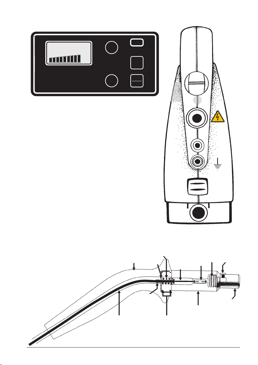
4.0 CONTROL PANEL LAYOUT
Probe Handle Diagram
Carbon Cored Lead “O” Rings
Screw Fitting
Neon
Lock Nut
End Cap
Neon Holder
Screw
Probe Handle Washer
Spring
1 LCD display (including battery condition
indicator)
2 Voltage control (10 turn)
3 Visual alarm indicates when fault is found
4 On switch
5 Off/test switch
6 Sensitivity control for the alarm
7 Audible alarm when fault is found
8 High Voltage probe connector
9 Fuse (1.6A slow blow) 5 x 20mm
10 Earth connection point
11 Charge connector – allows operation while
charging is in progress
12 Slide-off power pack
13 Earphone jack
5
Compact DC15 and DC30 POROSITY (HOLIDAY) DETECTORS - os
Aug 2002

Table 1. Suggested for High Voltage Spark Testing
Total Dry Film Thickness Suggested
Inspection
(µm) (mils) (V)
200 to 280 8 to 11 1,500
300 to 380 12 to 15 2,000
400 to 500 16 to 20 2,500
530 to 1,000 21 to 40 3,000
1,010 to 1,390 41 to 55 4,000
1,420 to 2,000 56 to 80 6,000
2,060 to 3,180 81 to 125 10,000
3,200 to 4,700 126 to 185 15,000
The above table should be taken as a GUIDE only. It is
recommended that the whole of this standard be used.
Table 1 below is derived from NACE standards and should be
used as a guide only.
5.0 Voltage Recommendations
International Standards
NACE RP0188-99 derived table
New Protective Coatings
on Conductive Substrates
ALLOW AN ADDITIONAL 200 VOLTS IF THE NEON IN THE PROBE HANDLE IS IN USE.
6os - Compact DC15 and DC30 POROSITY (HOLIDAY) DETECTORS Aug 2002

Table 2. kV Values from
NACE RP0490-2001
mm kiloVolts
0.250 1.650
0.280 1.750
0.300 1.800
0.330 1.900
0.360 1.950
0.380 2.050
0.410 2.100
0.510 2.350
0.640 2.650
0.760 2.900
Table 3. kV Values from
NACE RP0274-98
mm kiloVolts
0.51 6
0.79 7
1.6 10
2.4 12
3.2 14
4.0 16
4.8 17
13 28
16 31
19 34
The above tables should be taken as a GUIDE only. It is
recommended that the whole of this standard be used.
International Standards
NACE RP0490-2001 and RP0274-98 derived tables
Tables 2 & 3 below are derived from NACE standards and should
be used as a guide only.
Thin Film Pipeline
Coatings (FBE)
General Pipeline
Coatings
ALLOW AN ADDITIONAL 200 VOLTS IF THE NEON IN THE PROBE HANDLE IS IN USE.
7
Compact DC15 and DC30 POROSITY (HOLIDAY) DETECTORS - os
Aug 2002

HV Lead
Neon
Holder
18to22kresistance
W
6.0 TROUBLESHOOTING
In order to ensure that your Compact Porosity Detector is operating to
specification, the Detector handle and lead should be checked prior to use.
Use the following procedure:
Unscrew the neon holder from the handle.
Using a multi-meter, complete the circuit and check the resistance at both the
handle and the high voltage plug .
If resistance is outside the 18,000 to 22,000 ohm range, or is open circuit:
(a) Check and for either poor connection or damage;
(b) Check for break or damage to the HV lead .
Replace/rectify connection and leads and then re-test.
ÊË
ÊË
Ì
8os - Compact DC15 and DC30 POROSITY (HOLIDAY) DETECTORS Aug 2002
Ce manuel convient aux modèles suivants
1
Table des matières
Autres manuels PCWI Capteur de sécurité


