Paso PAW5500-VES Series Manuel utilisateur
User manual
Models:
PAW5502-V
PAW5504-V
PAW5506-V
Compact wall-mount
evacuation systems
PAW5500-VES
Cert. EN 54-16: 2008
n° 0068/CPR/101-2018
EN54
16

2
All PASO equipment is manufactured in accordance with the most stringent international safety standards and in compliance
with European Community requisites. In order to use the equipment correctly and eff ectively, it is important to be aware of all
its characteristics by reading these instructions and in particular the safety notes carefully.
WARRANTY
This product is warranted to be free from defects in raw materials and assembly. The warranty period is governed by the
applicable provisions of law. PASO will repair the product covered by this warranty free of charge if it is faulty, provided
the defect has occurred during normal use. The warranty does not cover products that are improperly used or installed,
mechanically damaged or damaged by liquids or the weather. If the product is found to be faulty, it must be sent to Paso
free of charges for shipment and return. This warranty does not include any others, either explicit or implicit, and does not
cover consequential damage to property or personal injury. For further information concerning the warranty contact your
local PASO distributor.
Important! Before using the equipment, make yourself aware of all characteristics by reading carefully the instructions
included in the printed manual or on the CD, paying particular attention to the safety notes.
MODEL: .............................................................................................................................................................................
SERIAL NUMBER: ............................................................................................................................................................
PURCHASE DATE: ............................................................................................................................................................

3
EN
PAW5500-VES
System manual PAW5500-VES Compact systems
TABLE OF CONTENTS
1. WARNINGS 4
1.1 Power supply and earthing 4
1.2 Safety notes 4
2. INTRODUCTION 5
2.1 Overview of the system 5
2.2 Functional features 5
2.3 Typical confi guration 6
3. GENERAL DESCRIPTION 7
3.1 Front panel 7
3.2 Inside view 8
4. INSTALLATION AND CONNECTIONS 9
4.1 Wall mounting 9
4.2 Connections 10
4.2.1 Connection of emergency units 11
4.2.2 Connection of paging units 11
4.2.3 Connection to other PAW5500-VES units 12
4.2.4 Connection of auxiliary input 12
4.2.5 Connection of music input 13
4.2.6 Connection of input contacts 13
4.2.7 Connection of relay outputs 14
4.2.8 21 to 29V connection 14
4.2.9 Connection of loudspeaker lines 14
4.2.10 Connection of standby amplifi er 15
4.2.11 Connection of power supplies 17
5. OPERATIONAL CONDITIONS AND TERMINOLOGY 18
5.1. Signalling of operating conditions 18
6. DEFINITIONS 18
7. MENU STRUCTURE 19
8. USING THE SYSTEM 20
8.1. Confi guration of the system 21
8.2. < MUSIC > Menu 25
8.3. < AUDIO SETTING > Menu 26
8.4. < INSPECTION > Menu 29
8.5. < OPERATOR > Menu 32
8.6. < CONFIGURATION > Menu 35
8.7. Criteria for managing priorities in emergency conditions 43
8.8. MANUAL emergency – < EMERGENCY > Menu 44
8.9. AUTOMATIC emergency (alarm status activated by an external peripheral unit) 46
9. FAILURE STATUS 47
9.1. System operation and signalling in a generic failure condition 47
9.2. System operation and signalling with a fault on a loudspeaker line 47
10. TECHNICAL SPECIFICATIONS 48

4
PAW5500-VES
EN
PAW5500-VES Compact systems System manual
1. WARNINGS
1.1 POWER SUPPLY AND EARTHING
These items of equipment are intended to work on a 230 VAC +10% / -15%, 50/60 Hz mains voltage and a 24 VDC supply
from the internal batteries.
! N.B. – FEATURES OF THE WIRING SYSTEM
The mains AC power MUST be supplied through a two-pole diff erential thermal-magnetic circuit breaker with a current
of 10 to 16A dedicated SOLELY to the equipment.
! N.B.
These devices have been designed to be connected to an earthed power supply.
Make sure that the equipment is always connected to earth in accordance with legal regulations.
1.2 SAFETY NOTES
All PASO equipment is made according to the strictest international standards and complies with European Union requisites.
For correct and eff ective use of the equipment it is important to be aware of all the characteristics by reading carefully these
instructions and warnings. While the equipment is in use, it is necessary to ensure adequate ventilation, above all leaving the
slits for providing air for the cooling fans free.
REFER TO THE ‘INSTALLATION AND CONNECTIONS’ SECTION FOR THE RELEVANT PROCEDURES, TO BE CARRIED
OUT BY TRAINED SPECIALISED PERSONNEL ONLY.
Important information for correct disposal of the product in accordance with EC Directive 2002/96/EC
his product must not be disposed of as urban waste at the end of its working life. It must be taken to a special waste
collection centre licensed by the local authorities or to a dealer providing this service. Separate disposal of electric
and/or electronic equipment (WEEE) will avoid possible negative consequences for the environment and for health
resulting from inappropriate disposal, and will enable the constituent materials to be recovered, with signifi cant
savings in energy and resources. As a reminder of the need to dispose of this equipment separately, the product is
marked with a crossed-out wheeled dustbin.
This product is in keeping with the relevant European Community Directives.

5
EN
PAW5500-VES
System manual PAW5500-VES Compact systems
2. INTRODUCTION
2.1 OVERVIEW OF THE SYSTEM
The new PAW5500-VES range incudes three integrated voice evacuation systems for emergency facilities, designed
specifi cally for wall-mounting and equipped with control units, certifi ed in compliance with EN 54-16:2008 / EN 54-4 standards.
Depending on the model, these systems are capable of managing from 2 to 6 alarm zones, each driven by a single amplifi er,
as well as remote microphone stations and controlled inputs to be connected to a central fi re-fi ghting system.
It is possible to connect up to a maximum of 6 of these systems to one other (for managing an overall maximum of 36 zones).
2.2 FUNCTIONAL FEATURES
•
Rated audio output: 500 W overall, distributable freely among the zones with a maximum limit of 250 W per single zone.
• Backlit 4.3” display with touch screen for selecting the alert and evacuation zones and enabling navigation for adjusting
volume levels, confi guring the equipment and viewing failures.
• Handheld fi reman’s paging microphone.
• Sending out of pre-recorded EVACUATION and ALERT messages.
• Sending out of pre-recorded BROADCAST messages (i.e. spots, announcements, sound bells).
• Playing back of pre-recorded messages via monitor loudspeaker.
• 7 off controlled input contacts, confi gurable for playing the evacuation and/or alert messages to the programmed zones or for
resetting the messages.
• 1 off music input for sound sources.
• 1 off auxiliary input confi gurable as a music source, a call with precedence activation or a call with automatic activation (VOX).
• 3 off confi gurable relay outputs.
• Double A+B output for each zone.
• Event log (list of failures and/or alarms that have occured in the system).
• Double LINK line for connecting other PAW5500-VES (up to a total of 6 units).
• Multilanguages management.
• Protected local button for placing the system in an emergency state, equipped with its own LED.
• Local reset button.
• 3-band equalisation for each zone output.
• 3-band equalisation for each music input.
• Optional internal expansion card ACPAW-2IN for two additional music inputs (EXT 1 and EXT 2).
• Optional internal expansion card ACPAW-6IN with DSP for six additional music inputs.
• Built-in SD/USB input for background music MP3 player.
• Independent selection on each zone of the various audio sources (MUSIC IN, AUX IN, MP3 player and EXT).
• Up to 8 pre-recorded messages can be retrieved from outside through input contacts (of which 2 fi xed emergency messages
- plus 6 that can be classed as emergency / evacuation / broadcast messages).
• Possibility of setting up to 16 timers for the programmed playing out of the broadcast messages with the possible activation of
signalling relays.
• Up to 16 PMB106-G and/or PMB112-G broadcasting microphone stations can be connected.
• Up to 4 of the above mentioned stations can be set for local calls only (zones of the card-cage to which they are connected).
• Up to 4 PMB132-V and PMB132/12-V remote emergency units can be connected (or, as an alternative, up to 2 touch screen
units TSB8500-V).
• EN54-4 certifi ed battery charge unit for 24VDC secondary power supply (batteries not included).
• Mounting on 19” rack (optional, with ACPAW-RCK accessory kit).
6
PAW5500-VES
EN
PAW5500-VES Compact systems System manual
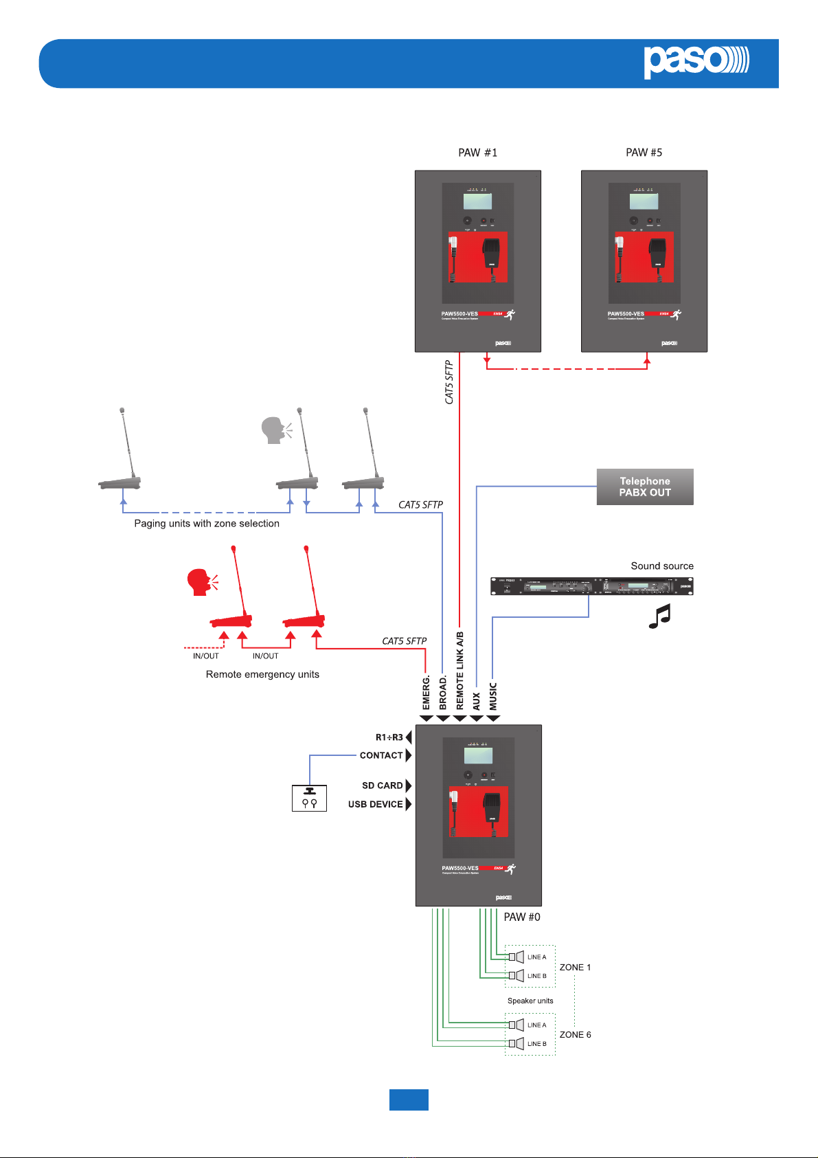
2.3 TYPICAL CONFIGURATION
7
EN
PAW5500-VES
System manual PAW5500-VES Compact systems
3. GENERAL DESCRIPTION
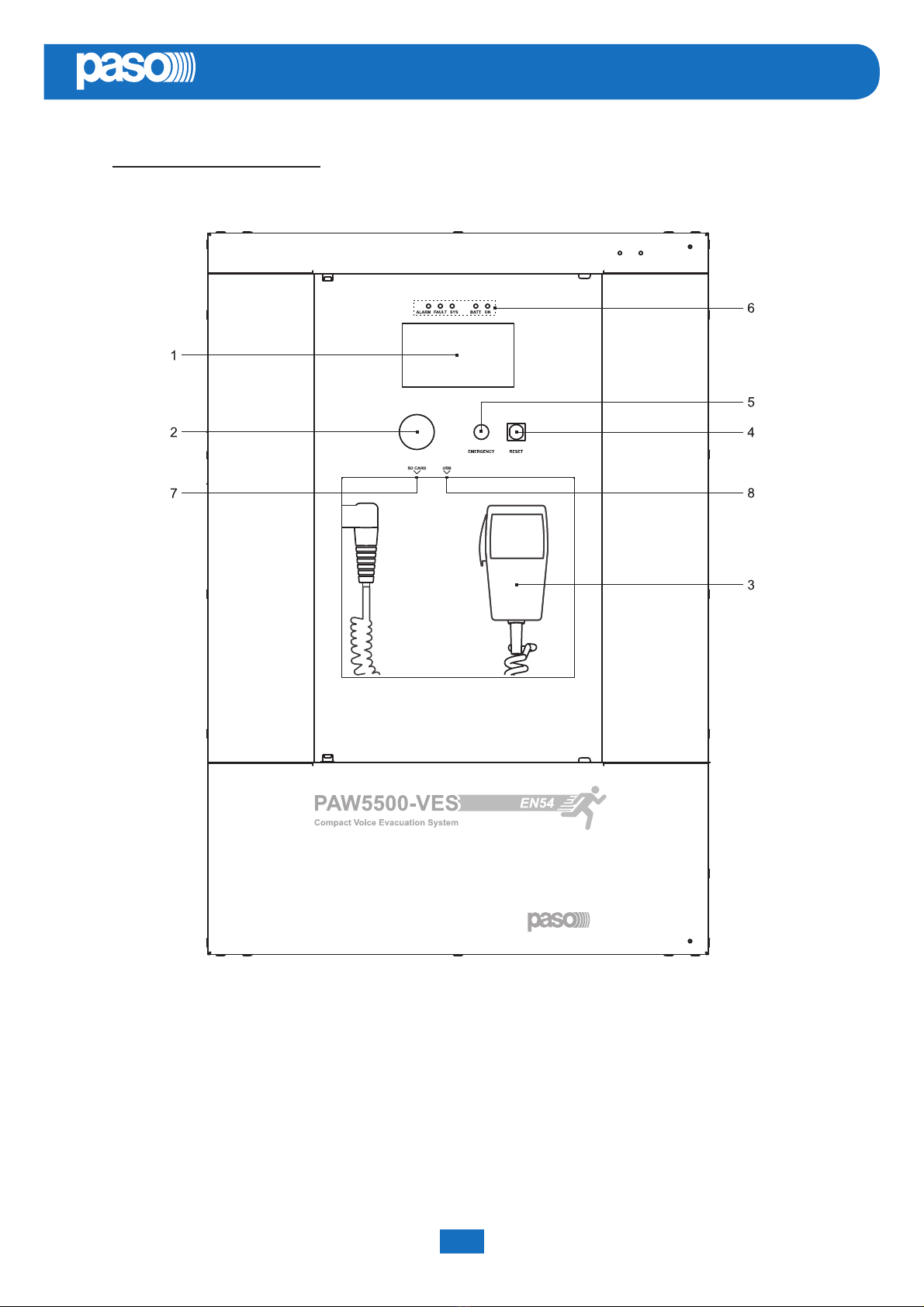
3.1 FRONT PANEL
1) Backlit 4.3” display with touchscreen for selecting the Alert/Evacuation zones and for navigation for adjusting volume
levels, confi guring the equipment and viewing failures.
2) Integrated loudspeaker for playing back the output signals from the zones or the signals of the input sources and for
replaying the acoustic signal indicating that a failure has been detected (beep). The signalling tone will be automatically
muted if the conditions of failure end. Furthermore, in accordance with the regulations, the beep is muted by the system
while the Emergency Microphone is being used.
3) Handheld fi reman’s paging microphone.
4) RESET button.
5) EMERGENCY button.
6) Status LEDs.
7) SD card slot.
8) USB socket for external device.
8
PAW5500-VES
EN
PAW5500-VES Compact systems System manual
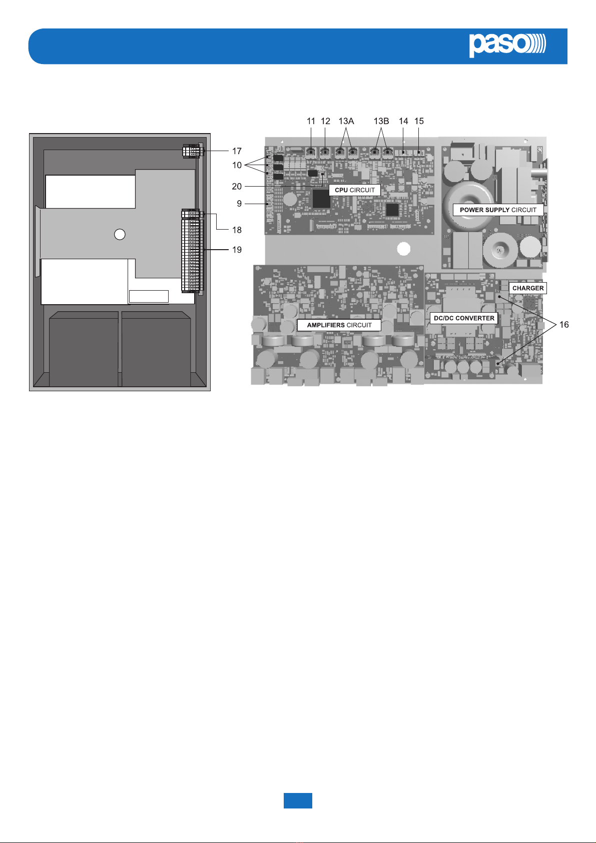
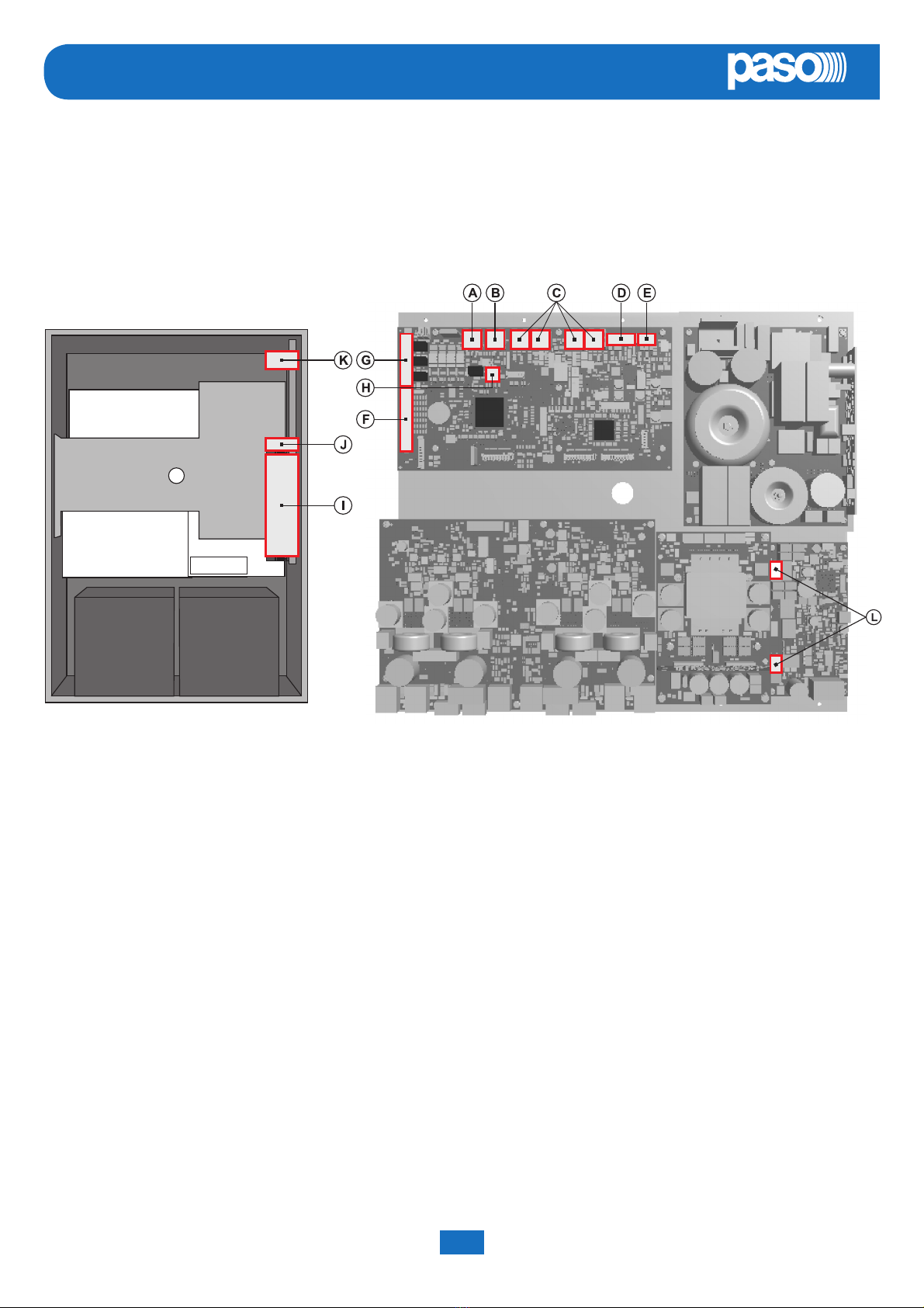
3.2 INSIDE VIEW
9) 7 off controlled input contacts.
10) 3 off relay output contacts.
11) Input for emergency microphone stations (max. 4).
12) Input for paging microphone stations (max. 16).
13) Input/output sockets REMOTE LINK A/B for connection to other PAW5500-VES units (overall max. of 6).
14) Input terminal strip for auxiliary sources with precedence contact.
15) Input terminal strip for music sources.
16) Connection to 24 VDC battery power.
17) Connection to 230 VAC power supply.
18) Connection of standby amplifi er.
19) Connection of loudspeakers lines.
20) Terminal strip for 21 to 29 V connection.

9
EN
PAW5500-VES
System manual PAW5500-VES Compact systems
4. INSTALLATION AND CONNECTIONS
! N.B.
Please remind that the operations illustrated in this part of the manual must be carried out by specialised personnel
ONLY, trained and qualifi ed in the equipment installation and maintenance. When the PAW is opened, parts entailing
a high risk of electric shocks become accessible.
It is advisable to install the equipment in a closed and sheltered place, protected against possible sources of damage (rain,
moisture, high temperatures, etc.).
Depending on requirements, the cables can be inserted by eliminating either the plugs sealing the holes in the top or the rear
door (in both cases use a fl at screwdriver or a cutter to lift them and remove them).
! It is important to keep the power cables separate from those dedicated to the other connections.
4.1 WALL MOUNTING
Take the cardboard template included in the package and position it
at a suitable height so that it is accessible to the user. Ideally, the front
display should be at eye level.
Having decided on the position, mark the fi ve points on the wall and fi t
Fischer wall plugs (min. Ø 9 mm) equipped with bolts into them.
Using the wall plugs as reference pins, lift the equipment and hook
it to the wall. It is advisable for this activity to be carried out by two
people.
Tighten the bolts.
NOTE:
For rack mounting, it is necessary to use the optional
accessory ACPAW-RCK and to follow the indications
provided on its instruction sheet.
10
PAW5500-VES
EN
PAW5500-VES Compact systems System manual
4.2 CONNECTIONS
! N.B.
Check that the main thermal-magnetic circuit breaker is switched OFF.
If it is not, switch it OFF before carrying out any other activities in the cabinet as there is a danger of electric shocks.
Proceed with connection of the various devices, referring to the appropriate points of the manual:
CPU circuit
A) Point 4.2.1 Connection of emergency units (page 11)
B) Point 4.2.2 Connection of paging units (page 11)
C) Point 4.2.3 Connection to other PAW5500-VES systems (page 12)
D) Point 4.2.4 Connection of auxiliary input (page 12)
E) Point 4.2.5 Connection of music input (page 13)
F) Point 4.2.6 Connection of input contacts (page 13)
G) Point 4.2.7 Connection of relay outputs (page 14)
(H) Point 4.2.8 21 to 29V connection (page 14)
AMPLIFIER circuit
H) Point 4.2.8 Connection of the loudspeaker lines (page 14)
I) Point 4.2.9 Connection of the standby amplifi er (page 15)
Once the basic connections have been made, it is possible to go on to connect the power supplies:
J/K) Point 4.2.10 Connection of power supplies (page 17)
! N.B.: It is essential to follow the correct sequence for powering up the equipment, failing which it could be
damaged.
Autres manuels pour PAW5500-VES Series
1
Ce manuel convient aux modèles suivants
3
Table des matières
Autres manuels Paso Système de sécurité


Manuels Système de sécurité populaires d'autres marques


EDM
EDM Solution 6+6 Wireless-AE Manuel utilisateur

Highway Safety Group
Highway Safety Group EA401 Manuel utilisateur

Siren
Siren LED GSM Manuel utilisateur

Detection Systems
Detection Systems 7090i Instructions de montage

Se-Kure Controls
Se-Kure Controls MicroMini SK-4841 Manuel utilisateur

Siemens
Siemens FDM273 Manuel utilisateur