Partlow MIC 1161 Manuel utilisateur

MIC 1161
1/16 DIN MICROBASED LIMIT CONTROLLER
OPERATORS
MANUAL
FORM 3535
EDITION 1
© JAN. 1995
PRICE $10.00
Brand
www.GlobalTestSupply.com
Find Quality Products Online at: sales@GlobalTestSupply.com

MIC 1161 Manual 2
Information in this installation, wiring, and operation manual is subject to change
without notice. One manual is provided with each instrument at the time of ship-
ment. Extra copies are available at the price published on the front cover.
Copyright © January 1995, The Partlow Corporation, all rights reserved. No part
of this publication may be reproduced, transmitted, transcribed or stored in a re-
trieval system, or translated into any language in any form by any means without
the written permission of the Partlow Corporation.
This is the First Edition of the MIC 1161 manual. It was written and produced
entirely on a desk-top-publishing system. Disk versions are available by written
request to the Partlow Publications Department.
We are glad you decided to open this manual. It is written so that you can take full
advantage of the features of your new MIC 1161 limit controller.
THE INTERNATIONAL HAZARD SYMBOL IS INSCRIBED ADJACENT TO
THE REAR CONNECTION TERMINALS. IT IS IMPORTANT TO READ
THIS MANUAL BEFORE INSTALLING OR COMMISSIONING THE UNIT.
!
NOTE:
It is strongly recommended that Partlow equipped applica-
tions incorporate a high or low limit protective device which
will shut down the equipment at a preset process condition
in order to preclude possible damage to property or prod-
ucts.
www.GlobalTestSupply.com
Find Quality Products Online at: sales@GlobalTestSupply.com

3 MIC 1161 Manual
Table of Contents
Section 1 - General Page
1.1 Product Description 5
Section 2 - Installation & Wiring
2.1 Installation & Wiring 7
2.2 Preparations for Wiring 9
2.3 Input Connections 17
2.4 Output Connections 19
Section 3 - Configuration & Operation
3.1 Operation 21
3.2 Configuration 26
Appendices
A - Glossary of Terms 32
B - Exploded View & Board Layout 36
Figure B-1 Exploded View 36
Figure B-2 CPU PWA 37
Figure B-3 Option PWA DC Output 3 38
C - Hardware Definition Code 39
D - Input Range Codes 41
E - Specifications 43
F - Model Number Hardware Matrix 47
G- Software Reference 48
www.GlobalTestSupply.com
Find Quality Products Online at: sales@GlobalTestSupply.com

MIC 1161 Manual 4
Figures & Tables
Figure 1-1 Display Illustration 6
Figure 2-1 Panel Cut-Out Dimensions 8
Figure 2-2 Main Dimensions 8
Figure 2-3 Panel Mounting 9
Figure 2-4 Noise Suppression 12
Figure 2-5 Noise Suppression 12
Figure 2-6 Wiring 16
Figure 2-7 AC Power 17
Figure 2-8 Thermocouple Input 17
Figure 2-9 RTD Input 17
Figure 2-10 Volt, mV mADC Input 18
Figure 2-11 Remote Reset Input 18
Figure 2-12 Remote Digital Connections 19
Figure 2-13 Relay Output 1 19
Figure 2-14 Relay Output 2 19
Figure 2-15 Relay Output 3 20
Figure 2-16 mADC Output 3 20
Table 3-1 Enable Mode Configuration Procedures 27
Table 3-2 Program Mode Configuration Procedures 28
Table 3-3 Set-Up Mode Configuration Procedures 30
www.GlobalTestSupply.com
Find Quality Products Online at: sales@GlobalTestSupply.com

5 MIC 1161 Manual
Product Description 1.1
1.1.1 GENERAL
This instrument is a microprocessor based single loop limit controller, user
configurable to either High Limit type or Low Limit type.
The input is user configurable to directly connect to either thermocouple,
RTD, mVDC, VDC or mADC inputs. The instrument can operate from a
90-264 VAC, 50/60 HZ power supply.
Features include fail safe operation (relay de-energized by the limit ex-
ceeded condition), front panel Reset switch, time limit exceeded display
and maximum/minimum tracking of excursions of the process variable.
1.1.2 DISPLAYS
Each instrument is provided with dual displays and status indicators as
shown in Figure 1-1. The upper display displays the value of the process
variable. The lower display displays the setpoint value. Status indication is
as shown in Figure 1-1, page 6.
1.1.3 ALARMS
Alarm indication is standard on all instruments. Up to two alarm outputs
are possible. Alarm type may be set as Process Direct or Reverse (high or
low), Logical Combination of the two alarms and Annunciator Direct or
Reverse. Alarm status is indicated by LED.
1.1.4 PROCESS VARIABLE/SETPOINT VALUE
RE-TRANSMISSION OUTPUT
If the instrument is specified with this option, this output may be scaled over
any desired range and re-transmitted.
www.GlobalTestSupply.com
Find Quality Products Online at: sales@GlobalTestSupply.com

MIC 1161 Manual 6
FIGURE 1-1
Keys and Indicators
AUTO
RESET
OUT EXCEED ALM
1161
TOP
www.GlobalTestSupply.com
Find Quality Products Online at: sales@GlobalTestSupply.com

7 MIC 1161 Manual
Installation and Wiring 2.1
Electrical code requirements and safety standards should be observed and
installation performed by qualified personnel.
The electronic components of the instrument may be removed from the
housing during installation. To remove the components, grip the side
edges of the front panel and pull the instrument forward. During re-installa-
tion, the vertically mounted circuit boards should be properly aligned in the
housing.
Ensure that the instrument is correctly orientated. A stop will operate if an
attempt is made to insert the instrument incorrectly.
CAUTION: This stop
can be over-ridden with enough force. If in doubt, check orientation
again!
Recommended panel opening sizes are illustrated in Figure 2-1, page 8.
After the opening is properly cut, insert the instrument into the panel open-
ing. Ensure that the panel gasket is not distorted and that the instrument is
positioned squarely against the panel. Slide the mounting clamp into place
on the instrument (see Figure 2-3, page 9) and push it forward until it is
firmly in contact with the rear face of the mounting panel.
Note: The mounting clamp tongues may engage either on the
sides or the top/bottom of the instrument housing. Therefore, when
installing several instruments side-by-side in one cut out, use the
ratchets on the top/bottom faces.
www.GlobalTestSupply.com
Find Quality Products Online at: sales@GlobalTestSupply.com

MIC 1161 Manual 8
FIGURE 2-1
Panel Cut-Out Dimensions
FIGURE 2-2
Main Dimensions
48 mm (1.89 in.)
48 mm
(1.89 in)
110 mm (4.33 in.)
Side View
10 mm (0.39 in.)
PANEL
CUTOUT
SIZE
45 mm +0.5 - 0.0
(1.77" +.024 - .000)
45 mm +0.5 - 0.0
(1.77" +.024 - .000)
www.GlobalTestSupply.com
Find Quality Products Online at: sales@GlobalTestSupply.com
9 MIC 1161 Manual
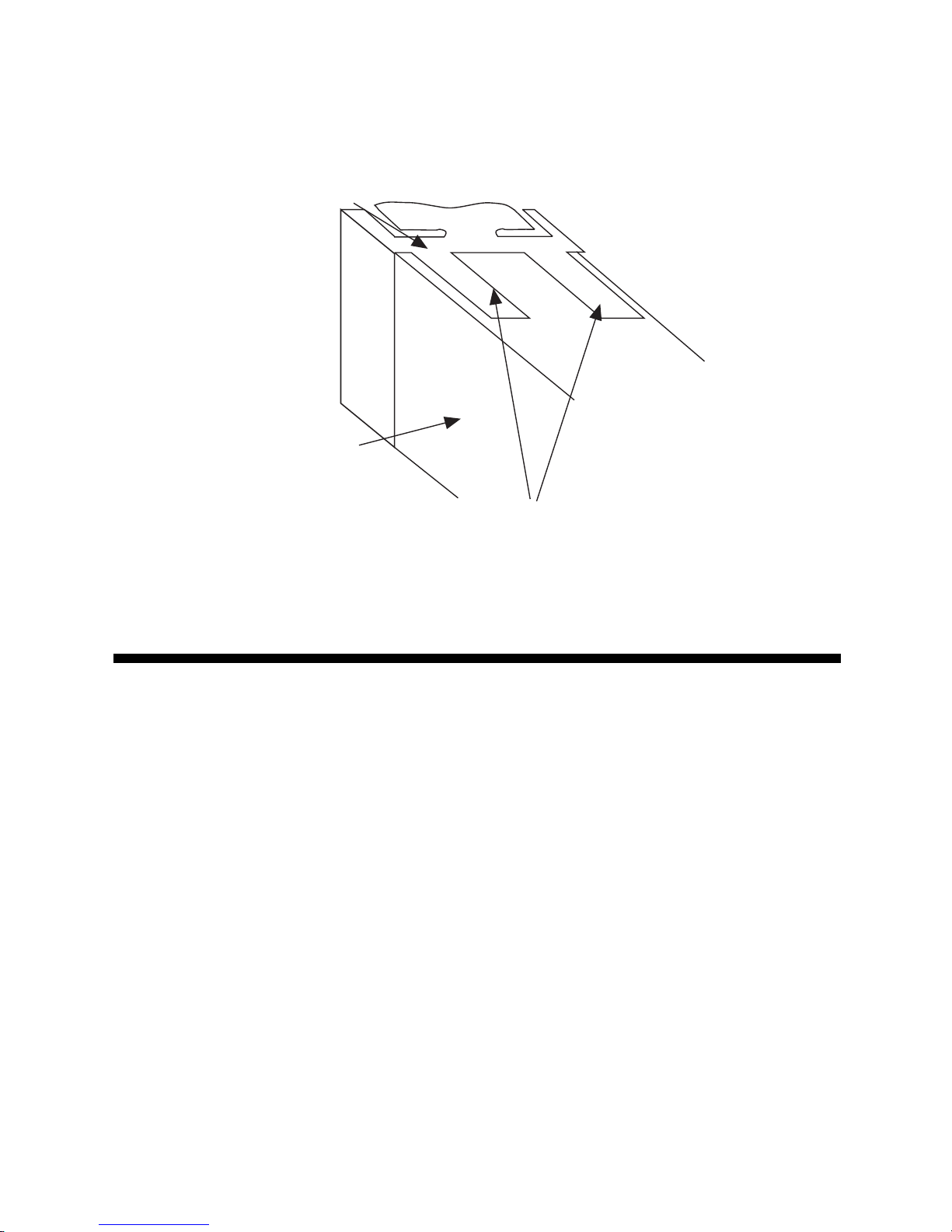
FIGURE 2-3
Panel Mounting the Controller
Preparation for Wiring 2.2
2.2.1 WIRING GUIDELINES
Electrical noise is a phenomenon typical of industrial environments. The
following are guidelines that must be followed to minimize the effect of
noise upon any instrumentation.
2.2.1.1 INSTALLATION CONSIDERATIONS
Listed below are some of the common sources of electrical noise in the
industrial environment:
• Ignition Transformers
• Arc Welders
• Mechanical contact relay(s)
• Solenoids
Mounting Clamp
Controller Housing
Tongues on mounting clamp engage in
ratchet slots on controller housing
www.GlobalTestSupply.com
Find Quality Products Online at: sales@GlobalTestSupply.com

MIC 1161 Manual 10
Before using any instrument near the device listed, the instructions below
should be followed:
1. If the instrument is to be mounted in the same panel as any of the
listed devices, separate them by the largest distance possible. For
maximum electrical noise reduction, the noise generating devices
should be mounted in a separate enclosure.
2. If possible, eliminate mechanical contact relay(s) and replace with
solid state relays. If a mechanical relay being powered by an
instrument output device cannot be replaced, a solid state relay can
be used to isolate the instrument.
3. A separate isolation transformer to feed only instrumentation should
be considered. The transformer can isolate the instrument from noise
found on the AC power input.
4. If the instrument is being installed on existing equipment, the wiring in
the area should be checked to insure that good wiring practices have
been followed.
2.2.1.2 AC POWER WIRING
Neutral (For 115 VAC)
It is good practice to assure that the AC neutral is at or near ground poten-
tial. To verify this, a voltmeter check between neutral and ground should be
done. On the AC range, the reading should not be more than 50 millivolts.
If it is greater than this amount, the secondary of this AC transformer sup-
plying the instrument should be checked by an electrician. A proper neutral
will help ensure maximum performance from the instrument.
2.2.1.3 WIRE ISOLATION
Four voltage levels of input and output wiring may be used with the unit:
• Analog input or output (i.e. thermocouple, RTD, VDC, mVDC, or mADC)
• SPDT Relays
• AC power
The only wires that should run together are those of the same category. If
they need to be run parallel with any of the other lines, maintain a minimum
6 inch space between the wires. If wires must cross each other, do so at
90 degrees. This will minimize the contact with each other and reduces
“cross talk”.
www.GlobalTestSupply.com
Find Quality Products Online at: sales@GlobalTestSupply.com
Table des matières
Autres manuels Partlow Contrôleurs


