Panoramic PC-1000 Manuel utilisateur
© Copyright 2008 Panoramic Corporation
PC-1000/Laser 1000 Service Manual
Panoramic Corporation Dental Panoramic/Cephalometric X-ray Machine
SM6000 Rev C

2© Copyright 2008 Panoramic Corporation
Table of Contents
Table of Contents..........................................................................................................................2-4
Introduction...................................................................................................................................5-6
Purpose.....................................................................................................................................5
Statement of Compatibility........................................................................................................5
Limited Warranty.......................................................................................................................6
Voltage Regulator Warning.......................................................................................................6
X-Ray Shielding Requirements.................................................................................................6
Pre-Installation Check .....................................................................................................................7
Electrical Requirements
Control Panel Orientation
Cephalometric Arm Orientation
Remote Switch
Darkroom Requirements
PC-1000 Installation
PC-1000 Components ..............................................................................................................8
PC-1000 Installation.............................................................................................................9-17
Tools Required.......................................................................................................9
Verify Power ..........................................................................................................9
Remove Packaging and Shipping Restraints........................................................9
Control Panel Relocation.......................................................................................9
Install Side Covers...............................................................................................10
Install Film Drum Assembly................................................................................. 11
Install Tubehead Assembly..................................................................................12
Install Temple Supports.......................................................................................12
Level Machine .....................................................................................................12
Perform mA Calibration .......................................................................................13
Perform Pulse Count Calibration....................................................................14-15
Perform X-ray Beam Alignment...........................................................................16
Install Top and Rear Covers................................................................................17
Complete Installation...........................................................................................17
PC-1000/Laser 1000 Installation
PC-1000/Laser 1000 Components .........................................................................................18
PC-1000/Laser 1000 Installation........................................................................................19-39
Tools Required.....................................................................................................19
Verify Power ........................................................................................................19
Remove Packaging and Shipping Restraints......................................................19
Control Panel Relocation.....................................................................................19
Install Side Covers...............................................................................................20
Install Film Drum Assembly.................................................................................21
Install Tubehead Assembly..................................................................................22
Install Temple Supports.......................................................................................22
Level Machine .....................................................................................................22
Install Cephalometric Arm....................................................................................23
Install Cephalostat Head Positioner ....................................................................23
Perform mA Calibration ..................................................................................24-25

3
© Copyright 2008 Panoramic Corporation
Table of Contents
PC-1000/Laser 1000 Installation (continued)
Perform Pulse Count Calibration....................................................................26-27
Perform Panoramic X-ray Beam Alignment.........................................................28
Remove Soft Tissue Shields................................................................................29
Perform Cephalometric X-ray Beam Alignment..............................................29-33
Perform Ear Rod Alignment............................................................................34-36
Install Soft Tissue Shield .....................................................................................37
Install Suggested Settings Decal.........................................................................37
Install Top and Rear Covers................................................................................37
Complete Installation...........................................................................................38
Notes.............................................................................................................................................39
Service Procedures
Remote Switch Installation......................................................................................................40
Screw Motor Height Limit........................................................................................................41
Screw Motor Assembly Exchange .....................................................................................42-43
Panoramic Radiography..................................................................................................Appendix A
Darkroom Procedures .....................................................................................................Appendix B
Manual Processing
Automatic Processing
Darkroom Light Leak Test
Loading The Panoramic Cassette
Loading The Cephalometric Cassette
Maintenance Schedule................................................................................................... Appendix C
PC-1000/Laser 1000 Labeling........................................................................................ Appendix D
PC-1000/Laser 1000 Specifications................................................................................Appendix E
PC-1000/Laser 1000 Space Requirements.....................................................................Appendix F
PC-1000/Laser 1000 Parts List ......................................................................................Appendix G
Final Assembly
Base Assembly
Main Chassis Assembly
Chinrest Arm Assembly
Head Support Assembly
Film Drum Assembly
Upper Belt Drive Assembly
Belt Drive Assembly
Roller Orbit Drive Assembly
Rotating Arm Assembly
Screw Motor Assembly
Tubehead Assembly
Electronics Assembly
Control Panel Assembly

4© Copyright 2008 Panoramic Corporation
Table of Contents
PC-1000/Laser 1000 Parts List (continued) ...................................................................Appendix G
Laser Collimator Assembly
Electromagnet Assembly
PC-1000/Laser 1000 Schematics................................................................................... Appendix H
System Wiring
Control Panel
Timer Circuit Board
X-ray Control
Laser Power/Control

5
© Copyright 2008 Panoramic Corporation
Purpose
Panoramic Corporation provides this printed manual as a guide for the operation of the PC-1000 dental
panoramic X-ray machine and the PC-1000/Laser 1000 dental panoramic/cephalometric dental X-ray
machine.
The PC-1000 will enable the user to take panoramic X-ray images. The PC-1000/Laser 1000 will enable
the user to take panoramic X-ray images, as well as cephalometric X-ray images. A laser alignment
device is incorporated into the PC-1000/Laser 1000.
The information contained in this manual is not all inclusive and Panoramic Corporation should be
contacted for assistance and clarification when necessary.
It is imperative that this equipment be installed, serviced, and used by personnel familiar with the
precautions required to prevent excessive exposure to both primary and secondary radiation. This
equipment features protective designs for limiting both the primary and secondary radiation produced
by the X-ray beam. However, design features cannot prevent carelessness, negligence, or lack of
knowledge.
Only personnel authorized by Panoramic Corporation are qualified to install and service this equipment.
Any attempt to install or service this equipment by anyone not so authorized will void the warranty.
Statement of Compatibility January 1, 1988
Please address any comments/questions concerning this statement of compatibility to:
Panoramic Corporation • 4321 Goshen Road • Fort Wayne, IN 46818 USA • Attn: Director of Engineering
The only components compatible with the PC-1000 are those supplied with the machine.
Regardless of possible statements made by other manufacturers, no one is authorized or certified to
make additions or deletions to this machine. Only the combination of components delivered with the
machine is certified compatible by the manufacturer. As compatible accessories become available, Pan-
oramic Corporation will certify them as compatible and make them available to the user.
Statement of Compatibility Addendum October 1, 1988
The Laser 1000 Cephalometric Attachment is certified by Panoramic Corporation to be compatible with
the PC-1000 dental X-ray machine, provided installation is performed by an authorized representative
utilizing specific installation instructions furnished by Panoramic Corporation.
Statement of Compatibility Addendum October 1, 1995
Laser 1000 Cephalometric Attachments manufactured after October 1, 1995 are compatible only with
Introduction

6© Copyright 2008 Panoramic Corporation
Introduction
Voltage Regulator Warning
Do not plug this machine into ANY voltage regulating device. Contact Panoramic Corporation with any
questions regarding this.
X-ray Shielding Requirements
The requirements for panoramic and cephalometric shielding for building, operator, and patient, depend
on state and local regulations. Contact your state Department of Health for compliance information.
Compliance could involve a blueprint review, facility check, wall construction, film badge implementation,
remote switch installation, and/or a lead apron. It is beyond the scope of this manual to advise on these
regulations.

7
© Copyright 2008 Panoramic Corporation
Pre-Installation Check
Electrical Requirements
Optimally, the PC-1000 and the PC-1000/Laser 1000 should have a dedicated 105-125 VAC, 20Acircuit
with line regulation of 5% or better. If a dedicated circuit is not available, a regular 20 A circuit will work
as long as it is not taxed by other loads beyond 5 A. A standard 115 VAC, three-wire, grounded, electrical
outlet should be installed by an electrician behind the machine.
Control Panel Orientation
The control panel on the PC-1000 and the PC-1000/Laser 1000 is mounted directly on the side of the
machine and requires no separate installation, wiring, or mounting. Although the control panel is mounted
on the patient's left side from the factory, it can be easily relocated to the opposite side during installation.
Verify with the doctor on which side the control panel should be located.
Cephalometric Arm Orientation
The cephalometric arm for the PC-1000/Laser 1000 is shipped in a separate box and can be mounted on
either side of the machine. Verify with the doctor on which side the cephalometric arm should be located.
Remote Switch
Some states and local governments require that the exposure switch to be remotely installed. A remote
switch kit is available from Panoramic Corporation. Refer to Appendix G for detailed procedures.
Darkroom Requirements
Proper darkroom facilities must be present before installing the PC-1000 or PC-1000/Laser 1000. The
darkroom will be used to process test films at the time of installation to verify proper calibration. Refer to
Appendix A for darkroom requirements and processing procedures.
8© Copyright 2008 Panoramic Corporation
PC-1000 Components
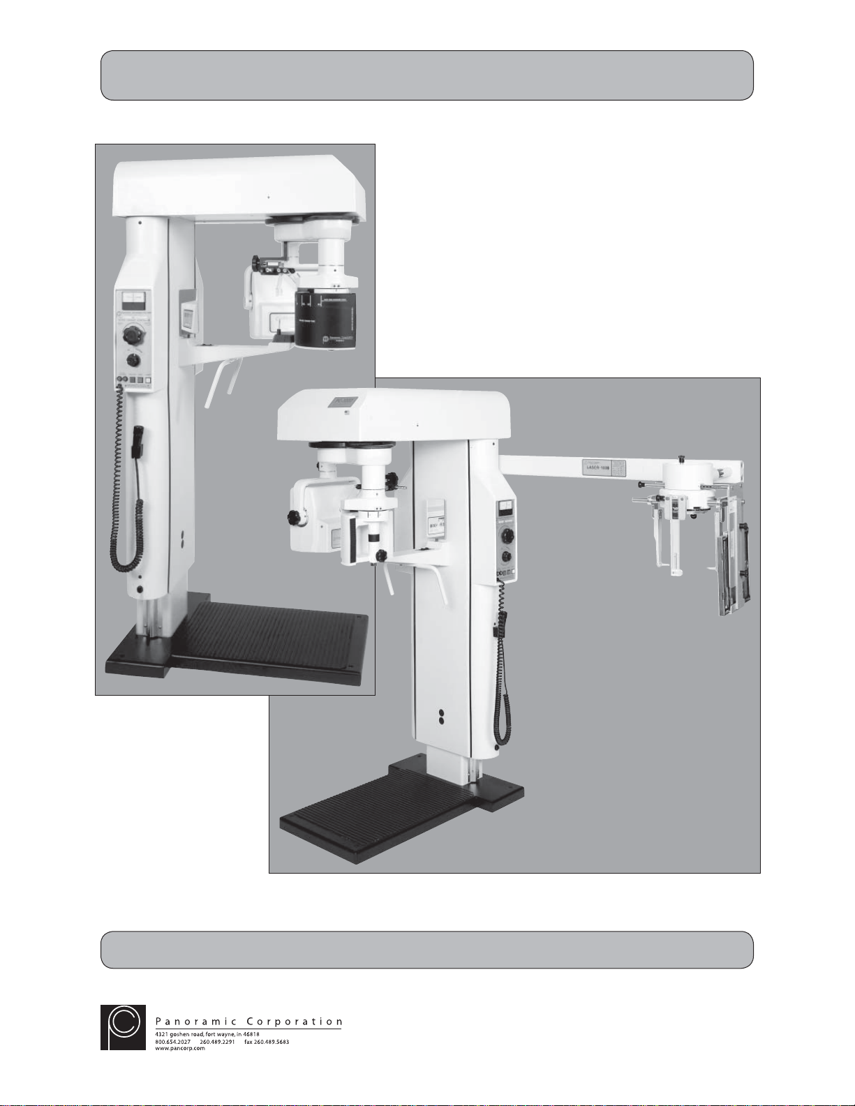
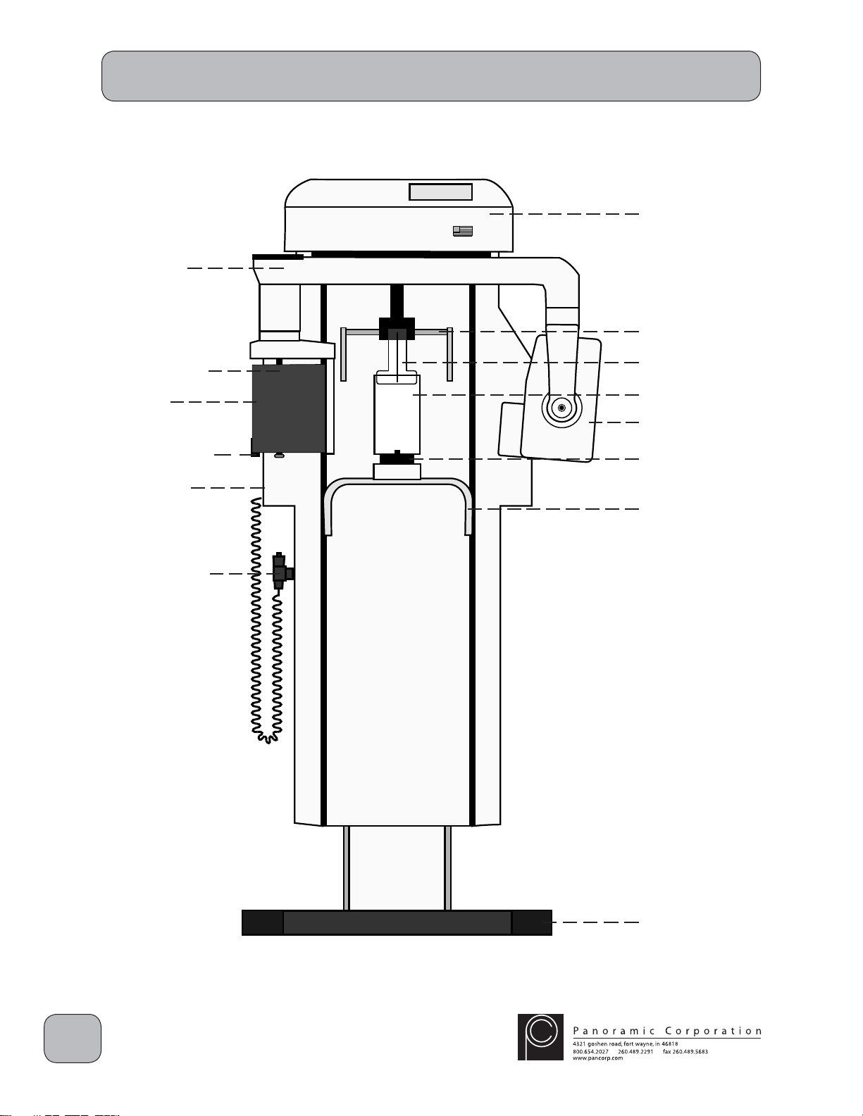
PC-1000
Top Cover
Temple Supports
Forehead Support
Mirror
Tubehead
Chinrest
Handles
Base
Rotating Arm
Cassette Sleeve
Film Drum
kVp Setting
Knob
Control Panel
9
© Copyright 2008 Panoramic Corporation
PC-1000 Installation
If there is any question concerning
installation or calibration, please
contact Panoramic Corporation
immediately.
Tools Required
Multimeter, regular and phillips screwdrivers, allen
wrenches, small fluorescent screen, knife, level,
and a pulse counter or stopwatch.
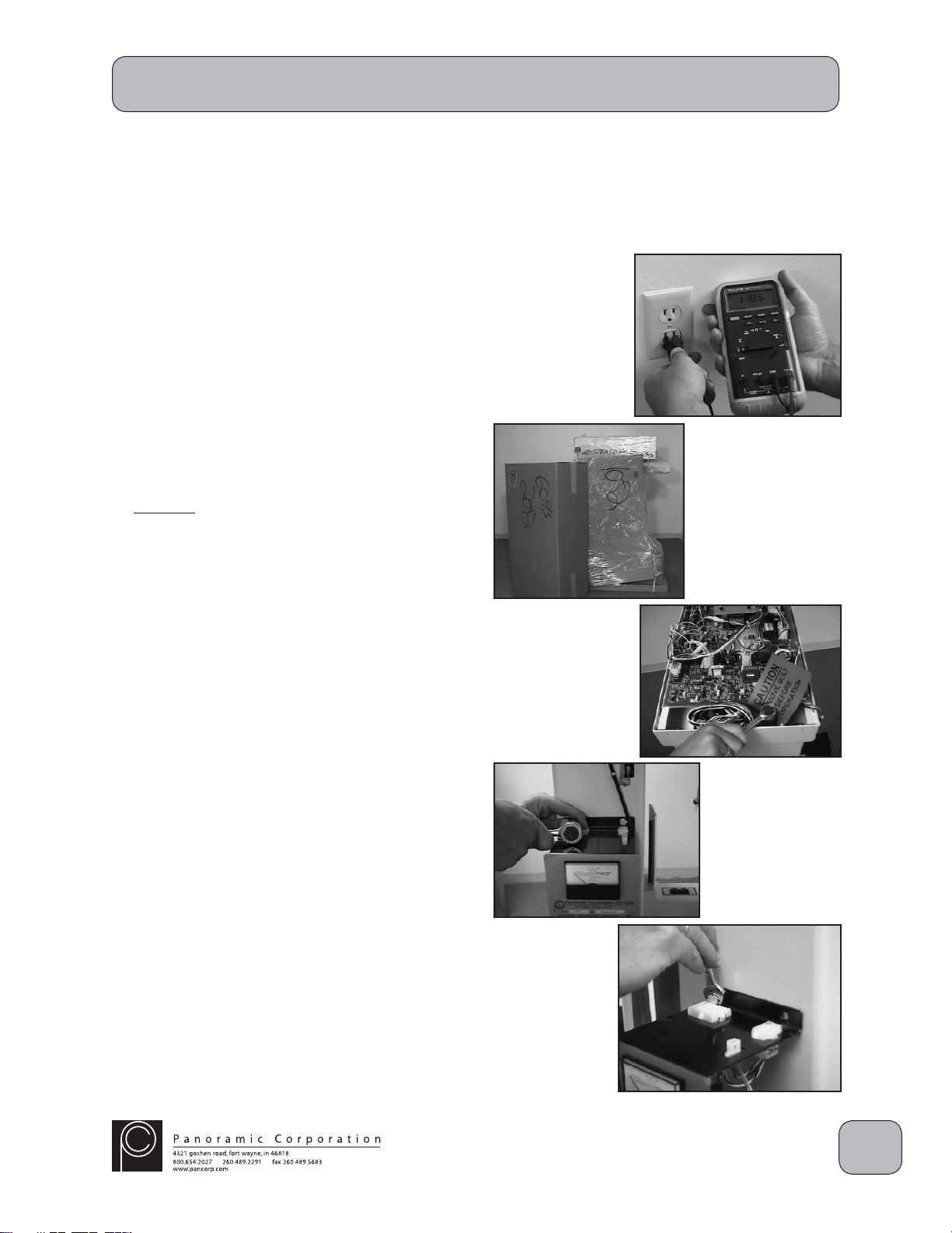
Verify Power
Verify that the outlet is a 110 VAC grounded outlet.
Remove Packaging and Shipping Restraints
1. Carefully remove all shipping packaging from
the PC-1000, including the plastic wrap,
cardboard, and wooden cover. Unpack the
side and top covers shipped in the separate
box.
2. Remove the 3/4" hex head shipping bolt from
the top rear of the overhead chassis. The
shipping bolt is located between the aluminum
chassis and the rear of the machine. There
may be 1 or 2 shipping bolts. Leave these
bolts with the office for future relocation.
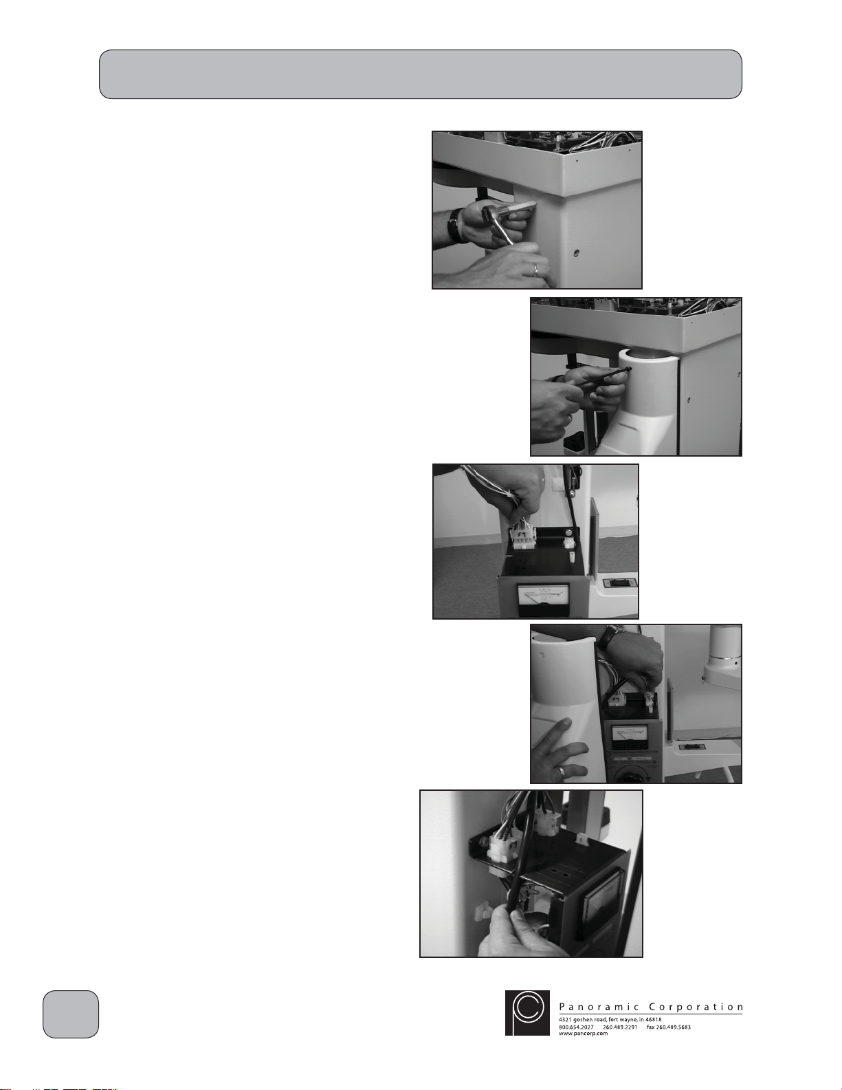
Control Panel Relocation
Verify with the doctor, on which side the control
panel needs to be located. To relocate it the
opposite side:
1. Remove the 4 7/16" mounting bolts from
the control panel.
2. Move the control panel to the opposite side
of the machine, while carefully routing the
wiring harness.
3. Reinstall the 4 7/16" bolts in the control
panel.
10 © Copyright 2008 Panoramic Corporation
Install Side Covers
1. Install 3 metal standoffs in the pre-threaded
holes on the side of the column opposite the
control panel.
2. Place the side cover without the power cord
over the standoffs.
3. Insert 3 allen head bolts into the holes in the
side cover and tighten into the metal standoffs.
4. Install 3 metal standoffs in the pre-threaded
holes on the control panel side of the column.
5. Locate the wire with the 15-pin molex
connector J7 in the overhead and connect it
to the 15-pin P7 connector on the top of the
control panel.
6. Connect the 6-pin molex connector P15 on the
main power cord in the side cover to the 6-pin
connector J15 on the top of the control panel.
7. Route the power cord through the notches on
the side of the control panel while placing the
side cover over the standoffs.
8. Insert 3 allen head bolts into the holes in the
side cover and tighten into the metal standoffs.
PC-1000 Installation
Ce manuel convient aux modèles suivants
1
Table des matières


