Panduit NET-SERV Series Manuel utilisateur

INSTRUCTIONS CM408F
© Panduit Corp. 2009-2011
FOR TECHNICAL SUPPORT www.panduit.com/resources/install_maintain.asp
NET-SERV Cabinets
Page 1 of 24

INSTRUCTIONS CM408F
For Technical Support: www.panduit.com/resources/install_maintain.asp
TableofContentsͲNetͲSERVCabinets
CabinetOperation Page
AccessoryGuide.....
3
Leveling....
4
Ganging..
5
AntiͲTipBracketsͲFloorMounting.. 6
Grounding.
7
EquipmentRailAdjustment
8
CableManagementBracketsandFingers 9
CableManagementPanelandLͲRetainers
10
VerticalBlankingPanels 11
SingleHingeDoor
12
SingleHingeDoorHandleDirectionReversal 13
SplitDoors
14
SidePanelInstallation.
15
POUMountingBrackets
16
POUMountingBracketLocations
17
VerticalPatchPanelBracketInstallation
18
OverheadCableOpenings.
19
VerticalExhaustDuctMounting. 20
CabinetSealing
21Ͳ23
Page 2 of 24
NOTES:
Casters can support a fully loaded cabinet. However, the casters should only be used to move the cabinet from one location to
another. To ensure maximum stability, the leveling legs should be used to support the cabinet when it is in the permanent location.
Not all features are included with all Net-SERV configurations.
INSTRUCTIONS CM408F
For Technical Support: www.panduit.com/resources/install_maintain.asp
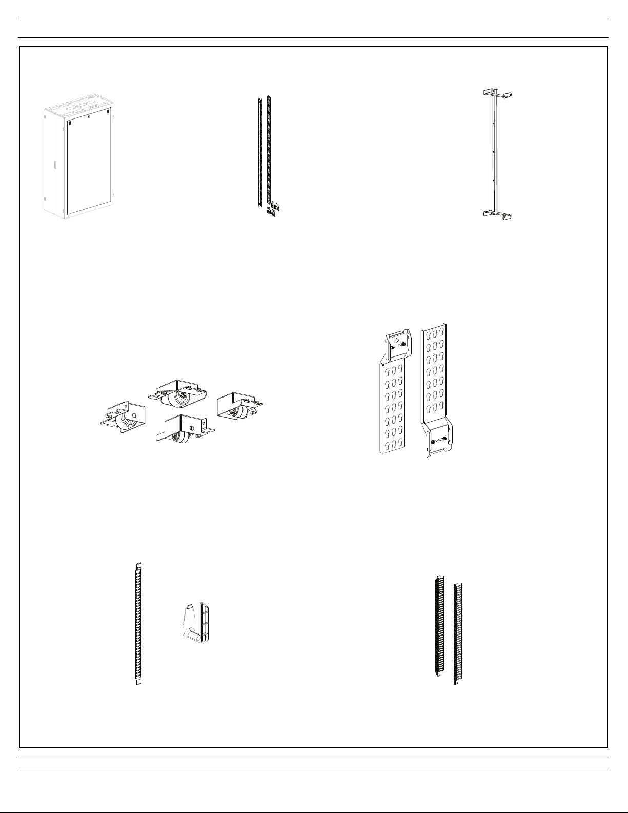
Accessory Guide
Page 3 of 24
Cabinet Side Panel
(S22PS, S52PS)
Casters
(SCSTR)
POU Brackets
(SVPDUB)
Cage Nut Equipment Rails and Brackets
(S62RC, S65RC, S72RC, S75RC)
Cable Management Finger Bracket and Fingers
(S62BRFK, S65BRFK, S72BRFK, S75BRFK)
Cable Management Panel and L-Retainers
(S62BRCK, S65BRCK, S72BRCK, S75BRCK)
Vertical Patch Panel Bracket
(SVPPB)
[6] L-Fingers and [1] CMSRC2
are included per panel

INSTRUCTIONS CM408F
For Technical Support: www.panduit.com/resources/install_maintain.asp
Page 4 of 24
Leveling
With the leveling legs fully retracted, use two people to slide the cabinet into the desired location. Lower the leveling legs using a
3/8” (10mm) deep well socket, until the cabinet weight is fully supported. Use a bubble level placed on the base rails in the locations shown to
adjust legs until the cabinet is level. For ganged cabinet applications, ensure that adjacent cabinets are adjusted to the same height, parallel
with each other, and no gaps at the top or bottom between cabinets.
3/8” socket
Note: The maximum weight load of the cabinet is 2500 pounds (1134 kg). The weight load should be evenly distributed across the height of
the cabinet, with the heaviest components mounted at the bottom of the cabinet.
Front-to-Back Cabinet Leveling
3/8” socket
Side-to-Side Cabinet Leveling

INSTRUCTIONS CM408F
For Technical Support: www.panduit.com/resources/install_maintain.asp
Page 5 of 24
Ganging
IMPORTANT:
If side panels are going to be used between cabinets, install (if needed) prior to ganging
cabinets as shown on page 15.
IMPORTANT:
Ensure cabinets are level by following the guidelines on page 4. Leveling the cabinet prior
to ganging is important to ensure proper door operation.
Secure the cabinets with two (2) top ganging brackets and (2) bottom ganging brackets
with two (2) #10-32 trilobular screws per bracket in the locations shown.
#10-32 Trilobular Screw
Ganging Bracket
#10-32 Trilobular Screw
Ganging Bracket
IMPORTANT:
Ensure tops of cabinets are touching prior
to ganging. Do not cinch the cabinets
together with the ganging hardware.
Top Ganging
Location
Bottom Ganging
Location
600mm/700mm Spacing
24” Spacing

INSTRUCTIONS CM408F
For Technical Support: www.panduit.com/resources/install_maintain.asp
3.2” [82mm]
4.0” [102mm]
B
A
C
D
10.5” [267mm]
E
Width Depth A B C D E
23.6" [600mm] 47.2" [1200mm] 23.6" [600mm] 47.2" [1200mm] 40.7" [1035mm] 9.8" [250mm] 45.2" [1148mm]
27.6" [700mm] 47.2" [1200mm] 27.6" [700mm] 47.2" [1200mm] 40.7" [1035mm] 11.8" [300mm] 45.2" [1148mm]
23.6" [600mm] 39.3" [1000mm] 23.6" [600mm] 39.3" [1000mm] 33.6" [853mm] 9.8" [250mm] 37.3" [947mm]
27.6" [700mm] 39.3" [1000mm] 27.6" [700mm] 39.3" [1000mm] 33.6" [853mm] 11.8" [300mm] 37.3" [947mm]
Cabinet Dimensions Mounting Distances
Page 6 of 24
Anti-Tip Brackets - Floor Mounting
NET-SERV Cabinets, whether stand alone or ganged with other cabinets, must always be anchored to the floor. The frame anchors
directly to the concrete slab or threaded rod via the included anti-tip brackets.
Assembly Sequence
1. Install the anti-tip brackets to the inside of cabinet frame, using (2) 5/16” bolts (1/2” socket) per bracket as shown below. Brackets
are slotted to allow for raising and lowering of cabinet. (See leveling instructions on Page 4)
2. Attach the anchors to the floor with appropriate hardware for your type of floor. See Floor Anchoring Footprint view and chart below
for floor mounting dimensions.
NOTE: Floor mounting bracket to be used when casters or leveling legs are installed. Bracket is to be reversed when casters are
installed. Reverse side of bracket allows for higher adjustment range with casters on cabinet frame.
Floor Anchoring Footprint
Anti-Tip
Brackets
Anti-Tip Bracket
(Bracket to be reversed
when casters are installed)
5/16” Bolts
(use 1/2” socket)
Floor Anchor Mounting
Locations
Frame
Mounting
Locations

INSTRUCTIONS CM408F
For Technical Support: www.panduit.com/resources/install_maintain.asp
Page 7 of 24
Grounding
The grounding locations for connection to the CBN (Common Bonding Network) are shown below. Remove masking from desired grounding
location (see detail below). Attach grouding lug with (2) #12-24 screws. Grounding jumpers are pre-installed between cabinet frame and rear
split doors and are included in all NET-SERV configurations that ship with split doors installed on cabinet.
Grounding Lug Locations
Grounding Lug
Location Detail
Remove masking and
attach grounding lug
with 2) #12-24 screws

INSTRUCTIONS CM408F
For Technical Support: www.panduit.com/resources/install_maintain.asp
Page 8 of 24
Top Location
Equipment Rail Adjustment
Loosen (2) 5/16” bolts at top of equipment rail bracket and (2) 5/16” bolts at bottom of equipment rail bracket to release clamping pressure
to allow for front to back rail adjustment. Reposition rails and tighten (4) 5/16” bolts to 14ft.-lbs (19.0 N-m).
Bottom Location
Loosen (2) 5/16” Bolts
to release clamping
pressure for front to
back rail adjustment
(use 1/2” socket)
Loosen (2) 5/16” Bolts
to release clamping
pressure for front to
back rail adjustment
(use 1/2” socket)
Equipment Rail
Bracket
Equipment Rail
Bracket

INSTRUCTIONS CM408F
For Technical Support: www.panduit.com/resources/install_maintain.asp
Page 9 of 24
Cable Management Brackets and Fingers
For precise positioning adjustment of cable management brackets, loosen (2) #12-24 hex head screws at top of bracket and (2) #12-24 hex
head screws at bottom of bracket using 5/16” socket. Adjust bracket position and retighten (4) #12-24 hex head screws. For large adjust-
ments, remove (4) #12-24 screws securing bracket to cabinet frame, reposition bracket, and secure cable management bracket with (4)
#12-24 hex head screws as shown.
Cable management fingers may be placed where desired by inserting the tabs on the rear of the finger sections into the mounting slots
located on the cable management brackets and then sliding downward. Reverse the process to remove cable management fingers.
Loosen (2) #12-24 Hex
Head Screws for precise
bracket adjustment
(use 5/16” socket)
Loosen (2) #12-24 Hex
Head Screws for precise
bracket adjustment
(use 5/16” socket)
Remove (4) #12-24 Hex Head Screws
(2-top, 2 bottom) for large cable
management bracket adjustments
(use 5/16” socket)
Cable Management
Finger Bracket
Cable Management
Finger

INSTRUCTIONS CM408F
For Technical Support: www.panduit.com/resources/install_maintain.asp
Page 10 of 24
Cable Management Panel and L-Retainers
For precise adjustment of cable management channel, loosen (2) #12-24 hex head screws at top of channel and (2) #12-24 hex head screws
at bottom of channel using 5/16” socket. Adjust channel position and retighten (4) #12-24 hex head screws. For large adjustments, remove
(4) #12-24 screws securing channel to cabinet frame, reposition channel, and secure cable management channel with (4) #12-24 hex head
screws as shown.
-CMSRC2 bend radius control clip can be installed in any of (6) indicated locations with (2) #12-24 Phillips screws as shown.
-Cable Management L-Retainers are to be installed where desired by inserting the tab on the rear of the L-Retainer into any keyed mounting
slot located on the cable management panel and then sliding downward while pulling release tab forward, as shown. Pull release tab and
reverse the process to remove L-Retainers.
Loosen (2) #12-24 Hex
Head Screws for precise
bracket adjustment
(use 5/16” socket)
Loosen (2) #12-24 Hex
Head Screws for precise
bracket adjustment
(use 5/16” socket)
Cable Management
Panel
Cable Management
L-Retainer (installed)
Keyed
Mounting
Slot
Release Tab
CMSRC2
(2) #12-24 Phillips
Screws
CMSRC2
Mounting
Locations
(6 Places)
Table des matières
Autres manuels Panduit Serveur


