OYN-X GateKeeper Manuel utilisateur

© Copyright OYN-X ®. All documentation rights reserved. 0
INSTALLATION MANUAL

© Copyright OYN-X ®. All documentation rights reserved. 1
Table of contents
Chapter Page Number
1. Contents of packaging 2
2. Plugging in the SD card into the Gatekeeper 3
3. Installing your Gatekeeper 4
4. Adjusting your Gatekeeper’s settings 7
5. Viewing recorded video 9
6. Technical Specifications 10
7. SD Card: Important information 11
8. Safety Precautions 12
9. FAQ (Frequently Asked Questions) 13

© Copyright OYN-X ®. All documentation rights reserved. 2
1. Contents of packaging
1. 1 x Gatekeeper motion light with video camera
2. 1 x Allen key
3. 2 x screws (within accessories bag)
4. 2 x plastic masonry plugs (within accessories bag)
5. 1 x 4G Micro SD card
Smartguard
Allen Key
Screws
Plastic Masonry plugs
SD Card
6. 1 x User Manual

© Copyright OYN-X ®. All documentation rights reserved. 3
2. Plugging in the SD card into the Gatekeeper
The main parts to the Gatekeeper are shown in Fig. 1.
Fig. 2 shows which direction you can adjust the PIR lens and by how many degrees.
Fig. 1 Fig. 2
1. Unscrew the waterproofed cover (See Fig. 3) using the provided Allen key, then insert the SD
card until it automatically locks into place.
2. If you need to remove the SD card, please press the OFF button and take it out within 30
seconds.
3. When SD card is being read the LED light turns green. Do not remove SD card whilst light is
green or data may be lost.
4. To remove SD card, push in SD card to eject. Once to unlocked then you can pull it out.
Fig. 3

© Copyright OYN-X ®. All documentation rights reserved. 4
3. Installing your Gatekeeper
IMPORTANT
IF IN ANY DOUBT ABOUT THE INSTALLATION OF THIS PRODUCT, CONSULT A QUALIFIED
ELECTRICIAN
- This product must be grounded
- Do not mount the unit against inflammable surfaces
- The motion detector will not operate correctly if it is installed:
Near the outlet of a central heating boiler
Near air conditioning plant
Pointing directly at moving vehicles
Within sight of reflections from moving water
Where other lamps could shine on the detector
IMPORTANT
BEFORE ATTEMPTING ANY INSTALLATION OR MAINTENANCE, ENSURE THAT THE
ELECTRICAL SUPPLY IS SWITCHED OFF AND THE CIRCUIT FUSES REMOVED OR THE
CIRCUIT BREAKER IS IN THE OFF POSITION.
Please make sure the voltage and polarity are correct before connection. Incorrect voltage may
cause electric shock. If you are not sure, please contact your retailer.
Note: It is recommended to mount the Gatekeeper Motion Light with Video Camera 2M
above the ground for optimum performance, do not mount the fixture below 1.2M. See
below figure for details of performance range.
Detection range: 10M x 160(see Fig. 4)
Fig. 4

© Copyright OYN-X ®. All documentation rights reserved. 5
1. Place plastic masonry plugs into the desired surface, aligning the holes as shown in Fig. 7.
Using an electric screwdriver, fasten waterproofed mounting plate directly to surface using
screws E.
2. Feed the waterproofed cable through the back mounting box and bush the cable entry to
avoid abrasion to the waterproofed cable.
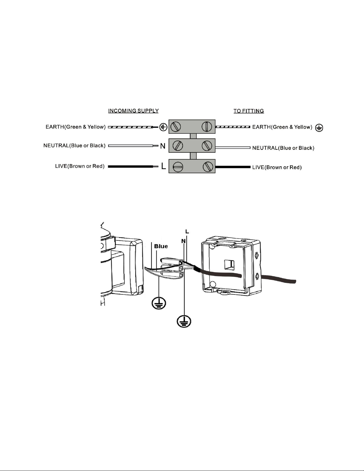
3. Wire the unit as follows (Fig. 5):
(Ensure all wires are connected securely and that no loose strands are exposed)
Fig. 5
4. Make sure the polarity is correct. Double check the connections after wiring (see Fig. 6).
Errors may damage the motion sensor or cause a fire hazard.
Fig. 6
5. Attach the unit to the waterproofed mounting plate, as also shown in Fig. 7. You will firstly
need to angle the unit back so that the catch at the top of the waterproofed mounting plate
fits into the slot on the back of the unit. Next lower the unit until holes at the bottom of the
waterproofed mounting plate and unit are flush. Then screw into this hole, tightening
carefully.
F
i
g
.
5
Brown

© Copyright OYN-X ®. All documentation rights reserved. 6
Fig. 7
Please allow 1 minute warm-up time after switching on. Push the RESET button after
switching on.
Remove plastic lens cover from camera after installation (see Fig. 8)
Fig. 8
F
i
g
.
7

© Copyright OYN-X ®. All documentation rights reserved. 7
4. Adjusting your Gatekeeper’s settings
Time control: Turn the time control knob to”+”
side to increase the illumination time (7 minutes
max.), turn the control knob to “-“ side to reduce
the illumination time (5 seconds minimum).
Walking Test: To perform a walk test turn the
knob fully to the “-“ side until the indicator faces
the “W” mark. When the walk test is completed
adjust the knob to the “+” side to your desired
lamp on time (we recommend this be at least 20
seconds to ensure lighting of the area is sufficient
for recording –20 seconds is marked as “ 20” on the product.
Dusk Level /Lux Setting: This setting is used to control the ambient light level at which
the motion security light turns on. You can set the light to turn on only in darkness by
turning the control fully clockwise to the “’’ sign position, or allow the security light to
trigger even during daylight by turning the control fully anti-clockwise to the “ ” sign
position, or choose a light level in between.
LED indicator: for indicating the function status of the unit by different color LED lights
(see Fig. 10).
Red: SD card is not inserted into the SD slot or the system is malfunctioning.
Green: The unit is recording or USB is inserted and connecting with the
computer
LED off: stand-by (SD card is inserted into the slot) when off/record button is
pressed
Please note when off/record button is pressed, remove SD card within 30 seconds
(now the LED will turn red after SD card is removed from the slot).
Fig. 10
Fig. 9
Fig. 9

© Copyright OYN-X ®. All documentation rights reserved. 8
Reset button: restore functions to default settings
1. Press RESET button once each time you turn on unit.
2. Please press this button in case of system malfunction.
Off/Rec: Please press Off/Rec button to remove SD card. Please remove card within 30
seconds of pressing the Off/Rec button to avoid loss of data.
Setting the day and time
This will allow the security video taken by Gatekeeper to display the correct date and time it was
taken.
1. Push TIME/DATE SET button (see Fig. 10) for 3 seconds, The LCD screen will then
flash 3 times, indicating you have entered Time/Date setting mode.
2. “YEAR”setting: “Y” and “08” are displayed on the screen; push the button to set
year from “08-99”, push the button again and hold for 3 seconds to scroll through
numbers quickly. If you have not pressed the button for 3 seconds, it will automatically
save the year and go on to allow you to set the month.
3. Repeat the same setting procedure for MONTH/DATE/HOUR/MINUTE (Note:
device will move quickly from one time & date setting to another, please be immediate
with inputting the correct settings).
4. “VIDEO/PHOTO ” setting: when entering this mode, these two icons and
“V” appear on the screen; push the button to choose ”V” (Video) or ”P”(Photo)*. If you
have not pushed any buttons for 3 second, “OK” will appear on the screen, indicating it
has automatically saved the current settings. The LCD screen will shut off automatically
10 seconds later.
* On the “P” (photo) setting, Gatekeeper will take a series of digital photographs at a rate of 3
photos every second when the motion sensor is triggered.
①
Start
②
YEAR
Setting
③
MONTH
Setting
④
DATE
Setting
⑤
HOUR
Setting
⑥
MINUTE
Setting
⑦
VIDEO/
PHOTO
Setting
⑧
Finish
Fig. 11

© Copyright OYN-X ®. All documentation rights reserved. 9
5. Viewing Recorded Video
Viewing image via a computer through a card reader (see Fig. 12)
1. Open the waterproofed cover on the Gatekeeper Motion Light with Video Camera
2. Press OFF/REC button and remove SD card from the slot.
3. Put the SD card into a card reader, connect PC and card reader by USB cable (not
included) and open any media player to view the video.
Fig. 12
Table des matières