OWC Mercury G4 Cube Manuel utilisateur
OWC Mercury G4 Cube Optical Drive
Installation Instructions
For the Power Macintosh
G4 Cube 450MHz/500MHz

Thank you for purchasing an OWC Mercury G4 Cube Optical Drive
from Other World Computing!
Please use this reference guide to install your OWC Mercury G4 Cube Combo Drive into
your Power Macintosh G4 Cube 450MHz/500MHz.
Before getting started, you will need the following:
• A well lit clean work space approximately 4’x3’
• A soft cloth or rubber mat to place the Cube on while working on it
• A #1 Phillips Screwdriver
• A Torx T-10 Screwdriver
• A Torx T-8 Screwdriver
• A blank CD-R disc
You will need to observe static safe precautions while performing this installation, just
like you would for installing memory into your computer. Refer to your original Power
Macintosh G4 Cube manual for those steps.
Take a few moments and align all of the components and tools you will need to perform
this upgrade so that you don’t have to move around much while doing the installation.
You will find that if you don’t have to reach very far for an item, it will allow you to
concentrate on the task at hand.

Begin by turning your G4 Cube over on it’s top. You will want to place the computer
on a soft cloth or a rubber mat to keep it from sliding around while you perform this
upgrade. A mouse pad works well, just be sure to not scratch the top of your Cube.
Press inward on the core retaining handle and release the locking mechanism as shown.
Remove the core from the outer shell and place the shell in a safe location so it will not
be in the way or get scratched. Press the core retaining handle back in, locking it in
place and turn the core over so the heatsink is facing up as shown.
Remove the 8 Torx T-10 screws as shown, note that screw #5 and #6 are longer than
the others and extend all the way into the latching mechanism. You will need to replace
them back into the same holes when completed.
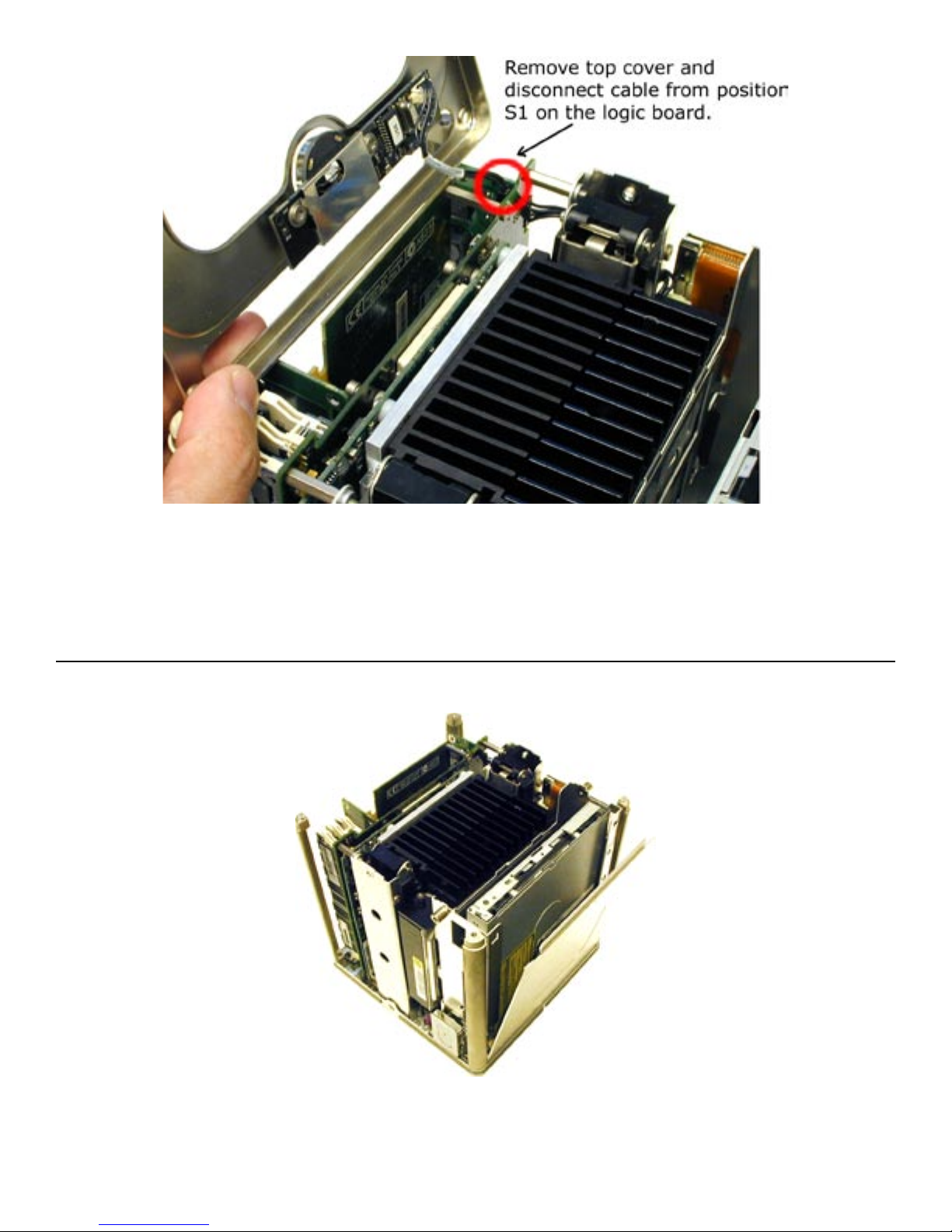
Gently remove the top cover, lifting it from the side that the optical drive is on. You will
notice a cable coming off of the sleep/power switch, which plugs into position S1 on the
logic board. Gently remove that cable from the logic board and set the top cover aside in
a safe location. The sleep switch plastic cover can fall out of it’s housing, if it does, put it
back in place.
There is a metal cover over the top of the optical drive that you need to remove to gain
access to it. Remove the metal cover by gently lifting up on it, releasing it from it’s slide
in tabs that you will see once it slides free. It slip fits into the bottom of the Cube core
and will easily come free once the tabs have been released. Set the cover aside.

Look at the side of the core that has the Airport card access door on it. If you have
an Airport card, you will need to remove it to gain access to this area. The Airport
card simply clips in and slides into it’s slot, with the antenna plugged into the end. For
instructions on how to install or remove the Airport card, refer to your Power Macintosh
G4 Cube manual.
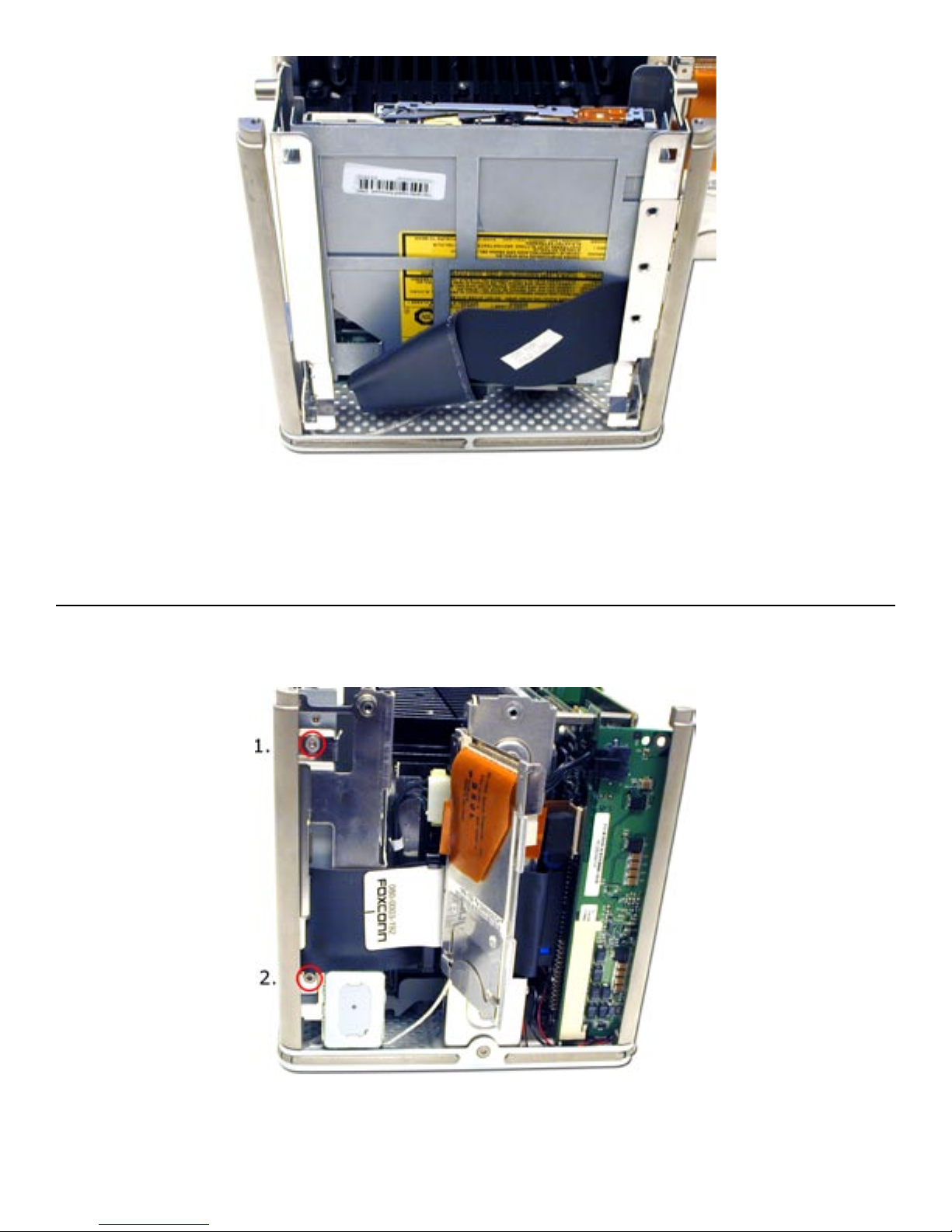
Open the Airport access door and unscrew the two Torx T-10 screws shown here. A
magnetized screwdriver helps greatly in this situation.
Turn the Cube around to the opposite side and remove the 2 remaining screws that
secure the optical drive.
Gently lift upward on the optical drive, it will slide in it’s track mount a bit. GENTLY
remove the IDE ribon cable from the backpanel connector. The IDE cable will detach
downward toward the bottom of the cube.
Then, remove the white power connector. That will pull straight toward you, and it will
take a gentle rocking motion to get it to release.
These steps require patience to avoid damaging the backpanel connector that attaches
to the drive. It is not a sturdy connection and in the next step you will understand why.
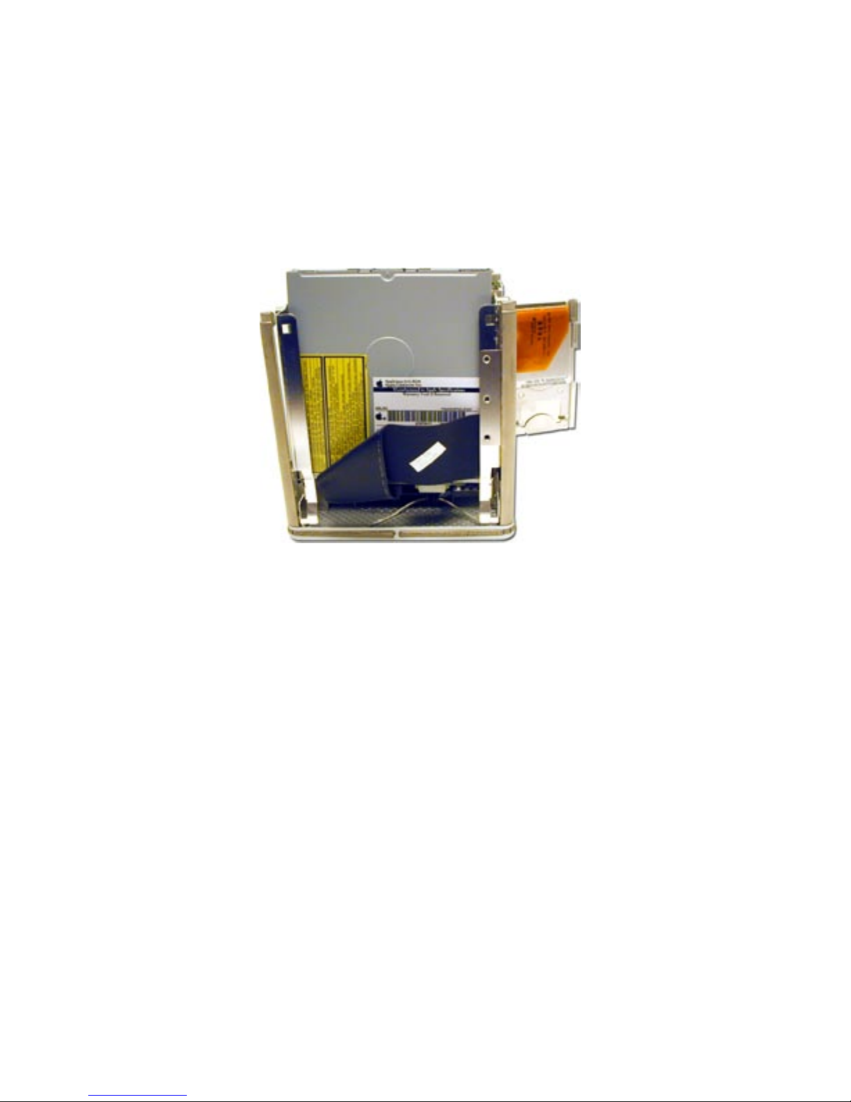
Once the stock optical drive is removed. place it on the table in front of you and look at
the backpanel connector. This will need to be removed and transferred to the new drive
you’re installing.
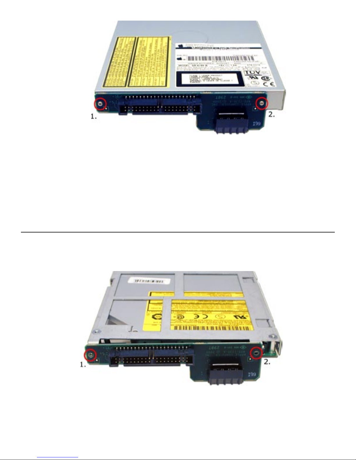
Notice that the screws that secure the backpanel connector to the drive are VERY small.
These screws have a tendency to not hold tight once removed. Unscrew the backpanel
connector and set the old drive and screws aside.
Align the backpanel connector onto the new optical drive as shown and press it’s
connector into place. You will see that it rocks back and forth a bit on the connector, you
will need to insert the included replacement screws to tighten it down properly.
We included these replacement screws, which have a larger diamater and head because
they eliminate the problem of the screws becoming loose over time completely.
Slide the new optical drive back down into the slot you removed it from, and reattach
the IDE and power cords. You may want to do the attachment with the drive lifted up a
bit in the slot, it does make for easier access for your fingers.
Replace the two Torx T-10 screws from the right side of the chassis. Notice one of the
holes is exact sized, and the other is eccentric to allow for adjustment, you won’t need
to adjust the depth at all, the custom bracketry that the drive uses is perfectly aligned
already. Close the Airport access door, and reinsert the Airport card (if equipped).

Reinsert the two Torx T-10 screws on the left side of the core.
Replace the access panel cover back onto the cube, sliding the two locking tabs back
down into place. Make CERTAIN that the cover is fully engaged and not loose at the
bottom. if the cover is not fully engaged, the core will become wedged in the chassis and
require expert service to repair it.
You may need to change the jumper on the internal hard drive to the Slave position.
Some original drives will not need this modifi cation, but you need to remove the drive to
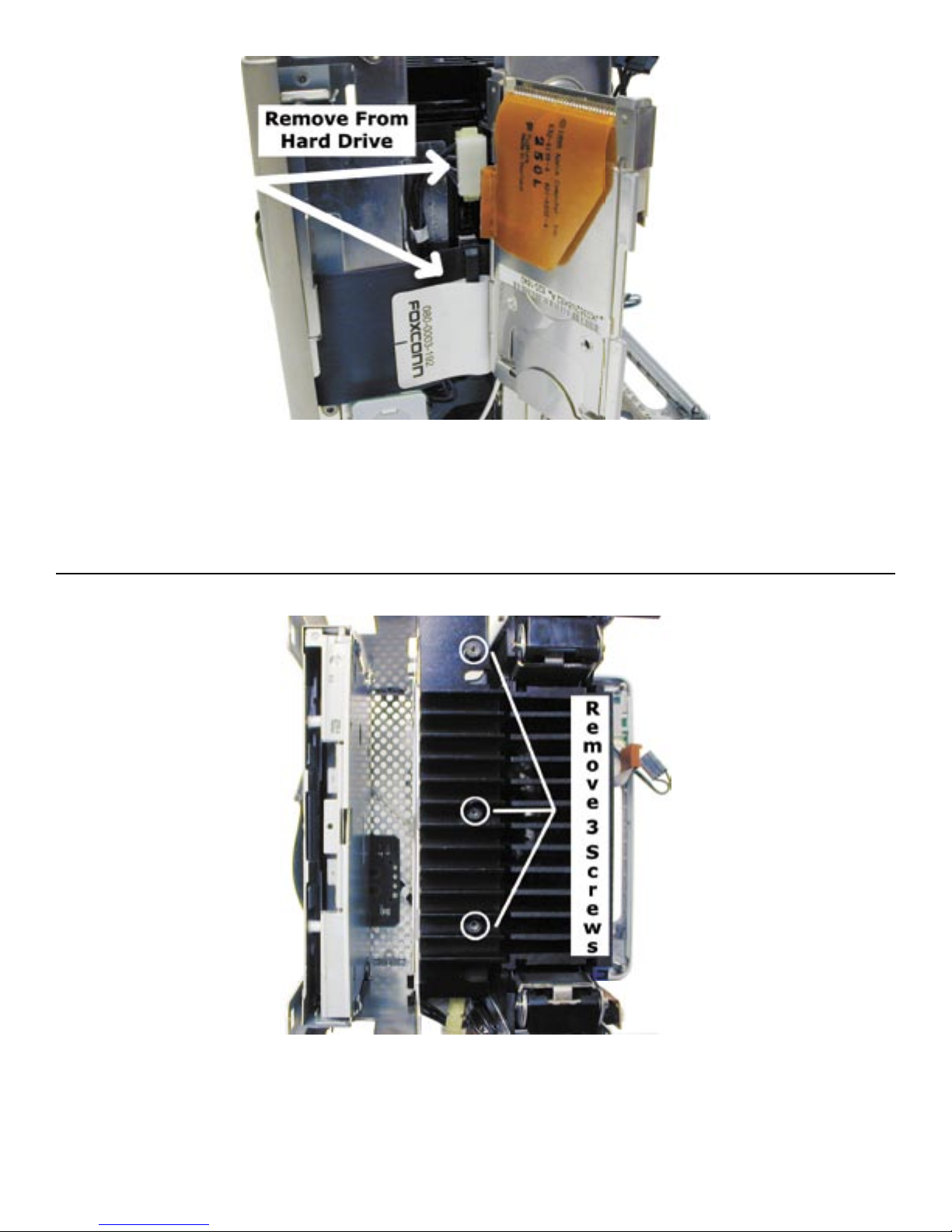
determine this. Behind the Airport door, you will see the 2 cables attached to the hard
drive. Remove those two cables, the power cable can take quite a bit of wiggling to get
it to release.
Look at the top of the core and remove the 3 screws from the heatsink attached to the
top of the drive, using a Torx T-8 Screwdriver. Slide the drive out of the chassis, and
look at the label on the drive identifying how to set it to Slave, usualy it is removal of
a jumper. Once that is complete, reinstall the drive, heatsink and cables. For a link to
diagrams of different hard drive jumper settings, see the troubleshooting section at the
end of this manual.
Table des matières
Autres manuels OWC Lecteur CD/CDR


Manuels Lecteur CD/CDR populaires d'autres marques


SmartDisk
SmartDisk Firewire CD-R/W Manuel utilisateur

Axis
Axis CD-ROM SERVER Manuel utilisateur

LG
LG CRD-8322B Manuel utilisateur

Memorex
Memorex 32023234 - 52x32x52x External USB2.0 CD... Instructions d'installation

Yamaha
Yamaha CD Recordable/Rewritable Drive CRW3200 Manuel utilisateur

Sony
Sony CRX230AE Manuel utilisateur


