Oriflow Rhino Manuel utilisateur
© Copyright 2015 ORIFLOW LLC
Operating Instructions for
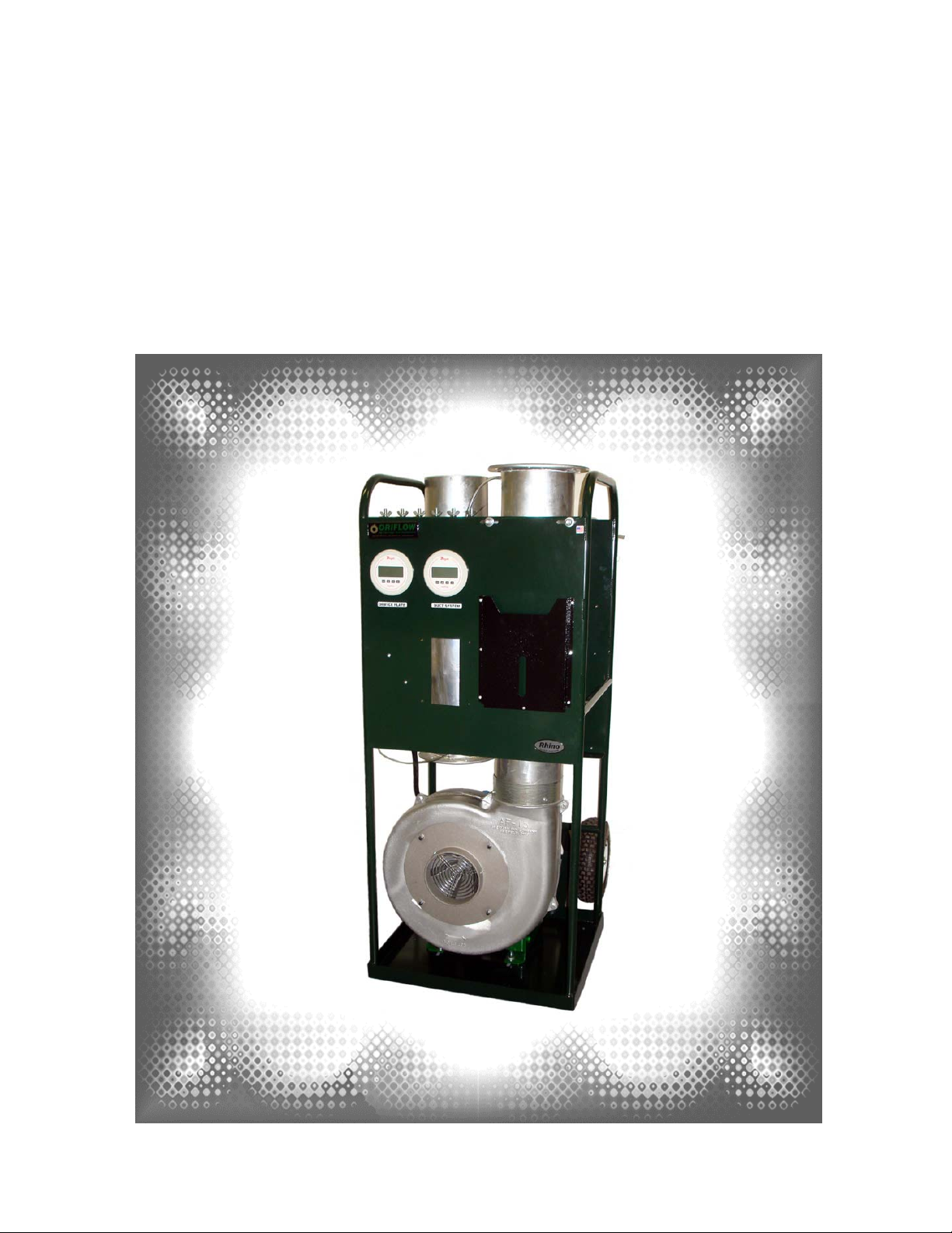
Rhino
Duct Leakage Tester
(Metric)

© Copyright 2018 ORIFLOW LLC Rev: 03-2018
1
Table of Contents
Introduction
Introduction ……………………………………….…….. 2
Safety Precautions
Safety Precautions ………………………………….…. 2
Prior to Testing
System Preparation …………………….………………. 3
Power Requirements …………………………………... 3
Extension Cord Requirements ………………………... 4
Flex-Duct Length ………………………………………... 4
Determining Maximum Allowable Leakage ….……... 4
Determining Which Orifice Plate to Use ……………... 5 - 7
Duct Leakage Test Setup and Procedure
Install Orifice Plate and Upper Tube Section………… 8 - 9
Connect Flexible Duct to Orifice Tube ……………….. 10
Connect Flexible Duct to Duct System ………………. 10
System Test Pressure Connection …………………… 11
Duct Leakage Test Setup (SUPPLY) ………………… 12
Duct Leakage Test Setup (RETURN/EXHAUST) ...….. 13
Inlet Transition Required for Return/Exhaust Testing . 14
Zeroing Pressure Gauges ……………………………… 15
Avoiding Over-Pressurization ………………………… 16
Obtaining System Test Pressure ……………………… 16 - 17
Determining Leakage Rate……………………………… 17 - 19
Troubleshooting
Zero reading on “DUCT SYSTEM” gauge ………….... 19
Zero reading on “ORIFICE PLATE” gauge …………….. 20
Can’t obtain system test pressure ……………………… 21
“ORIFICE PLATE” gauge reading maxed out………...... 21

© Copyright 2018 ORIFLOW LLC Rev: 03-2018
2
Introduction
These operating instructions are for ORIFLOW model RHINO air leakage tester.
Take pride in knowing that you have purchased the best air leakage tester on the
market. It is no secret that Oriflow manufactures the highest quality testers, and has
unparalleled customer service and technical support.
The orifice plates available for your duct leakage tester are constructed from laser-
cut 3.2 mm stainless steel and do not require recalibration for 10 years. Note the
authority having jurisdiction may override this requirement, and if so, Oriflow has very
reasonable rates for calibrating orifice plates manufactured by Oriflow.
Safety Precautions
Before operating your tester, read the following safety precautions:
DO NOT operate the tester in the rain,
DO NOT operate the tester while it is near or in water,
DO NOT operate the tester with a damaged electrical cord or plug,
DO NOT remove the inlet safety screen,
DO NOT touch the blower wheel when the unit is plugged in,
DO NOT look into the discharge end of the tester when the unit is plugged in,
DO NOT use the tester as a ladder or step stool,
DO NOT allow children near the tester,
DO use an extension cord of the proper gauge (see Table 2),
DO use the proper voltage and line frequency listed on the motor nameplate,
DO lock the caster when the tester is positioned horizontally,
DO use the tester on level ground,
DO secure the tester when transporting it,
DO wear proper hearing protection, safety glasses and work gloves,
DO seek assistance when lifting the tester (e.g., loading onto truck, going up
or down stairs).
© Copyright 2018 ORIFLOW LLC Rev: 03-2018
3
Prior to Testing
System Preparation
Cap off all ends of system using clear plastic and duct tape or sheetmetal duct end
caps. Make sure you test the part of the duct system that leakage testing is required.
Usually, this is from the system fan up to, but not including, the VAV boxes (terminal
units). Refer to the engineer's specifications and all applicable codes and test
standards.
Power Requirements
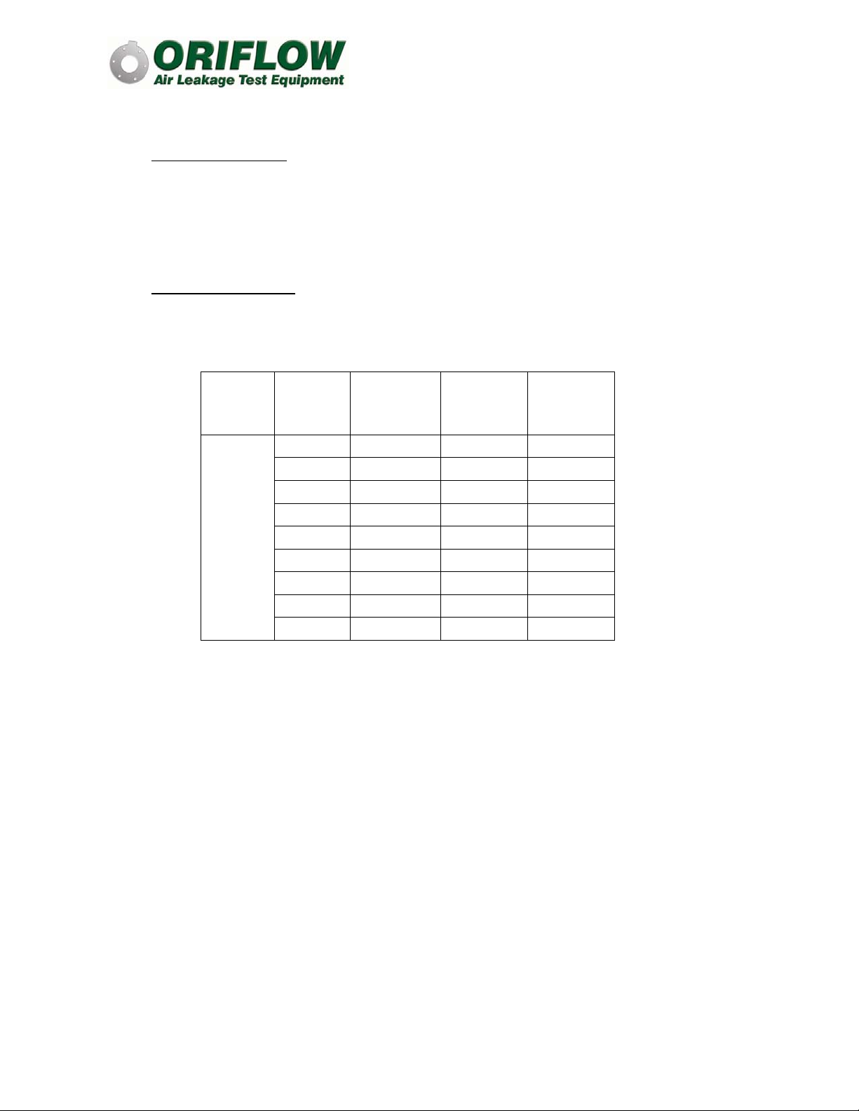
Do you have an adequate power supply for your tester (see Table 1)?
Table 1 – Tester Amp Draw
Tester
Model Voltage Flow
Control
Option Phase Full Load
Amps
Rhino
208 Slide Gate 3 13
208 VFD 3 14
230 VFD 1 21
230 Slide Gate 3 12
230 VFD 3 13
380 Slide Gate 3 7
380 VFD 3 8
460 Slide Gate 3 6
460 VFD 3 7
© Copyright 2018 ORIFLOW LLC Rev: 03-2018
4
Extension Cord Requirements
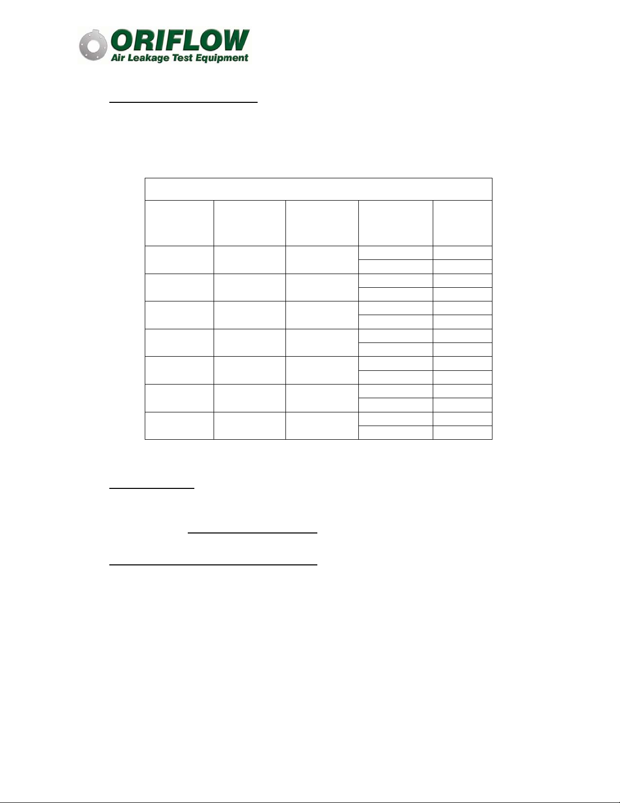
If you need an extension cord, is it the proper gauge? See Table 2 below for
extension cord requirements.
Table 2 – Required Extension Cord Wire Gauge
Rhino Model
Flow
Control
Option Voltage Phase
Extension
Cord Length
(meters)
Wire
Gauge
VFD 230 1 3 to 15 10
15 to 30 10
Slide Gate 230 3 3 to 15 14
15 to 30 14
VFD 230 3 3 to 15 14
15 to 30 14
Slide Gate 380 3 3 to 15 14
15 to 30 14
VFD 380 3 3 to 15 14
15 to 30 14
Slide Gate 460 3 3 to 15 14
15 to 30 14
VFD 460 3 3 to 15 14
15 to 30 14
Flex-Duct Length
Make sure you have enough flexible-duct with your tester for the job. Each tester
includes 3.8 m, which is enough for most applications. Extra lengths of flexible-duct
are available at www.oriflow.com/products.
Determining Maximum Allowable Leakage
To determine the maximum allowable leakage for the project, use ORIFLOW’s free
online programs to make these calculations (www.oriflow.com/programs).
Calculations are done for either of the two typical specifications: percentage of
system flow, or leakage class. If the specification uses leakage class, you will need
to calculate the total duct system surface area. Oriflow has a free Adobe form
available to our customers that will calculate duct surface area given the duct shape,
dimensions and length.
© Copyright 2018 ORIFLOW LLC Rev: 03-2018
5
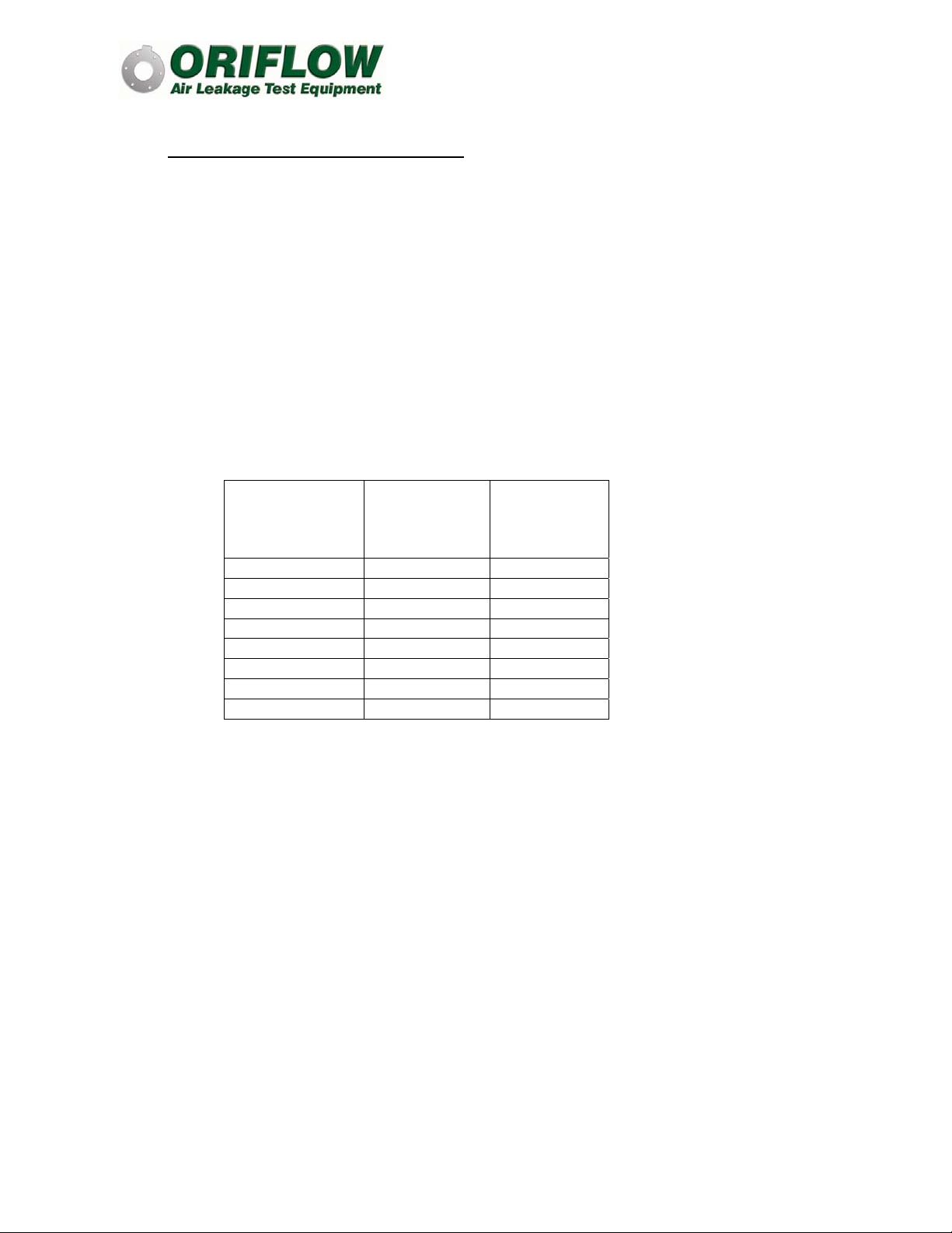
Determining Which Orifice Plate to Use
After determining the allowable leakage at the system test pressure, refer to the
following tables for the capacities of each orifice plate available for the RHINO model
tester. Make sure you have an orifice plate that can measure the maximum allowable
leakage. The proper plate is the one where the maximum allowable leakage falls
between the minimum and maximum leakage at the system static pressure. For
example, if you are testing a system at 2500 Pa pressure and the maximum
allowable leakage is 283 L/s, you will need a 125 mm orifice plate since the 125 mm
plate can be used for up to 380 L/s of leakage (see Table 7).
It is a good idea to have the next larger orifice plate size since it is common for duct
systems to leak more than the maximum allowable. Smaller diameter plates are use
when leakage is relatively low.
Table 3 – Tester Capacities using the 25 mm Orifice Plate
System Static
Pressure
(Pa)
Minimum
Leakage*
(L/s)
Maximum
Leakage
(L/s)
500 4 21
1000 4 19
1500 4 18
2000 4 17
2500 4 14
3000 4 12
3500 4 9
4000 4 6
© Copyright 2018 ORIFLOW LLC Rev: 03-2018
6
Determining Which Orifice Plate to Use (continued)
Table 4 – Tester Capacities using the 50 mm Orifice Plate
System Static
Pressure
(Pa)
Minimum
Leakage*
(L/s)
Maximum
Leakage
(L/s)
500 17 87
1000 17 78
1500 17 73
2000 17 66
2500 17 57
3000 17 47
3500 17 35
4000 17 26
Table 5 – Tester Capacities using the 75 mm Orifice Plate
System Static
Pressure
(Pa)
Minimum
Leakage*
(L/s)
Maximum
Leakage
(L/s)
500 40 195
1000 40 180
1500 40 165
2000 40 145
2500 40 130
3000 40 105
3500 40 80
4000 40 60
Table 6 – Tester Capacities using the 100 mm Orifice Plate
System Static
Pressure
(Pa)
Minimum
Leakage*
(L/s)
Maximum
Leakage
(L/s)
500 75 370
1000 75 340
1500 75 310
2000 75 280
2500 75 245
3000 75 195
3500 75 155
4000 75 105
© Copyright 2018 ORIFLOW LLC Rev: 03-2018
7
Determining Which Orifice Plate to Use (continued)
Table 7 – Tester Capacities using the 125 mm Orifice Plate
System Static
Pressure
(Pa)
Minimum
Leakage*
(L/s)
Maximum
Leakage
(L/s)
500 125 560
1000 125 520
1500 125 480
2000 125 430
2500 125 380
3000 125 310
3500 125 240
4000 125 175
Table 8 – Tester Capacities using the 159 mm Orifice Plate
System Static
Pressure
(Pa)
Minimum
Leakage*
(L/s)
Maximum
Leakage
(L/s)
500 215 730
1000 215 670
1500 215 630
2000 215 560
2500 215 510
3000 215 425
3500 215 310
4000 215 230
© Copyright 2018 ORIFLOW LLC Rev: 03-2018
8
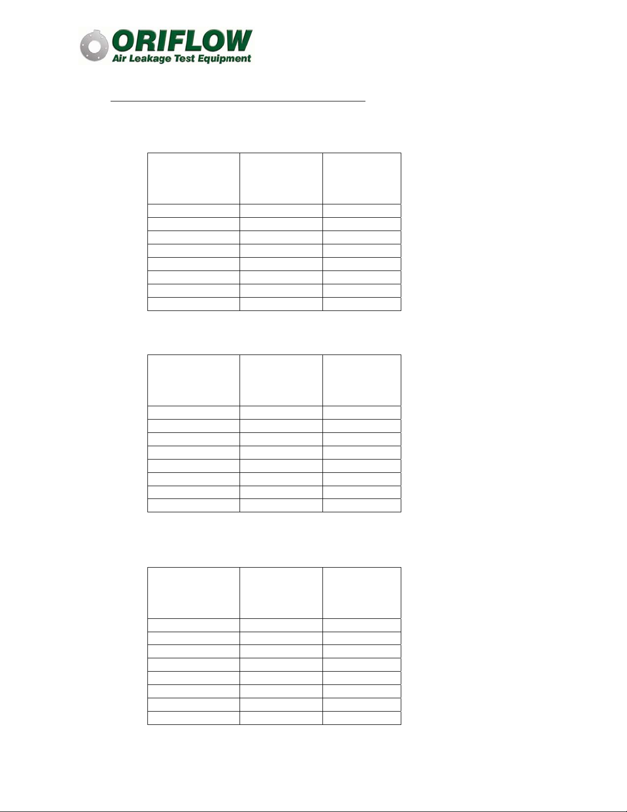
Install Orifice Plate and Upper Tube Section
The orifice plate that was determined from the previous section should now be
installed with the serial number facing upwards, so the corresponding calibration
certificate may be referenced after installation. Refer to Figures 1 through 4.
Figure 1 – Install Orifice Plate and then Rotate Clockwise
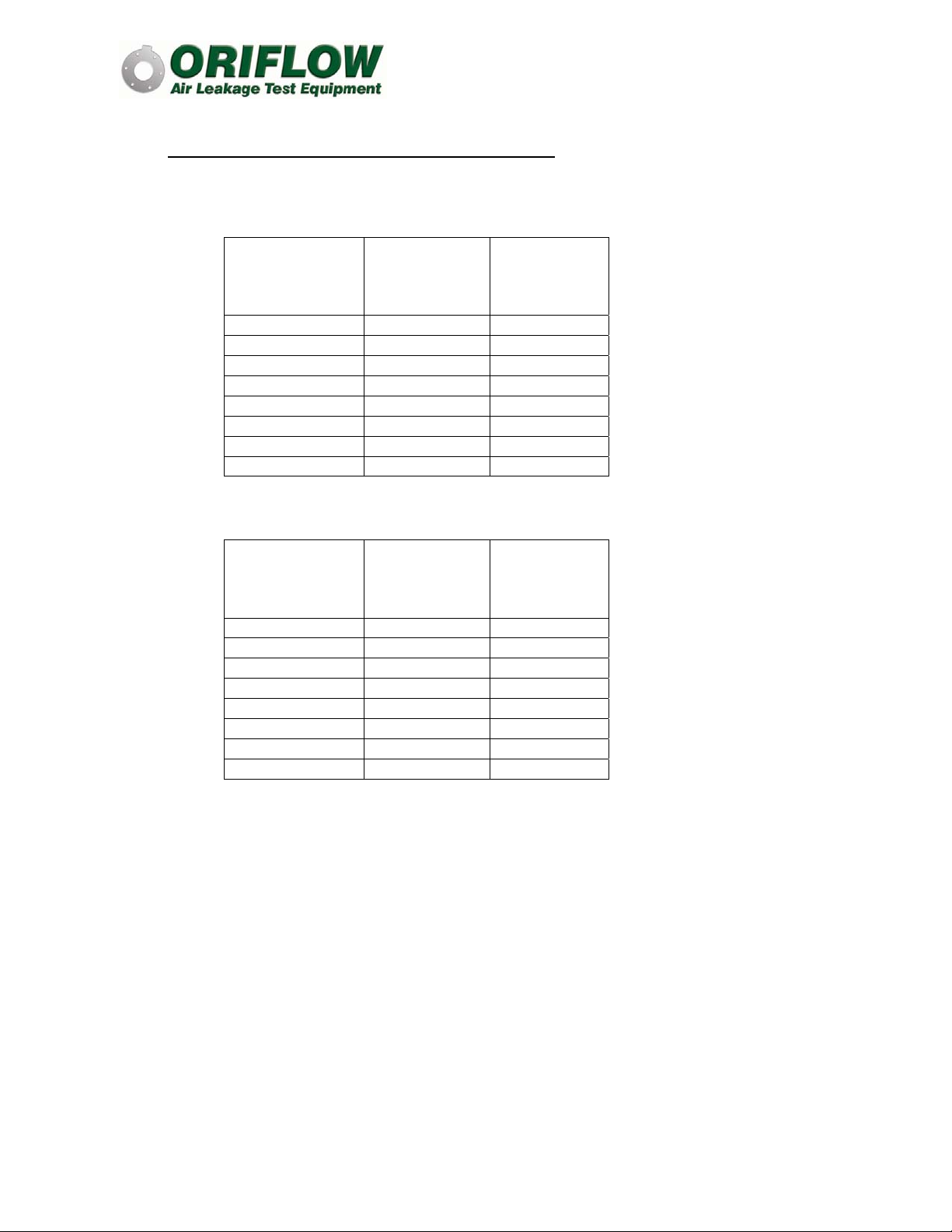
Figure 2 – Rotate Orifice Plate Clockwise until it Locks in Place
© Copyright 2018 ORIFLOW LLC Rev: 03-2018
9
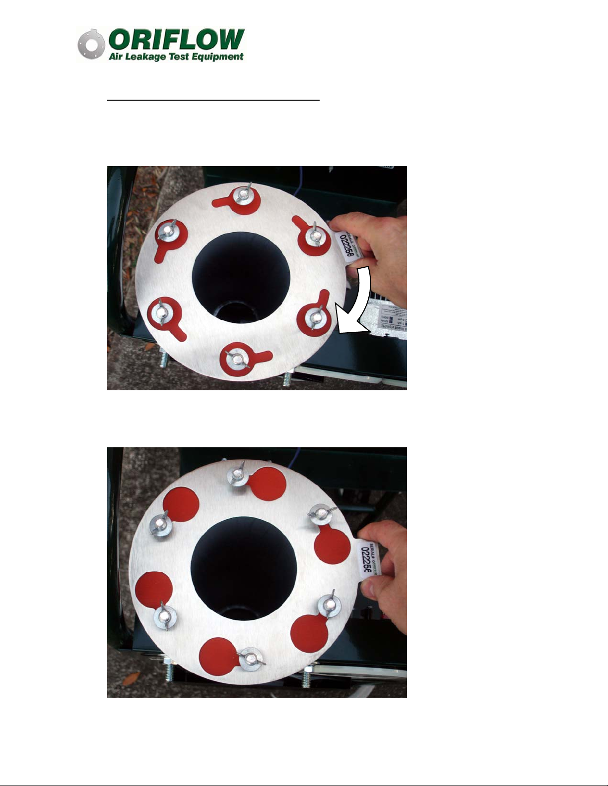
Install Orifice Plate and Upper Tube Section (continued)
After the orifice plate is locked in place, place the upper tube section over the
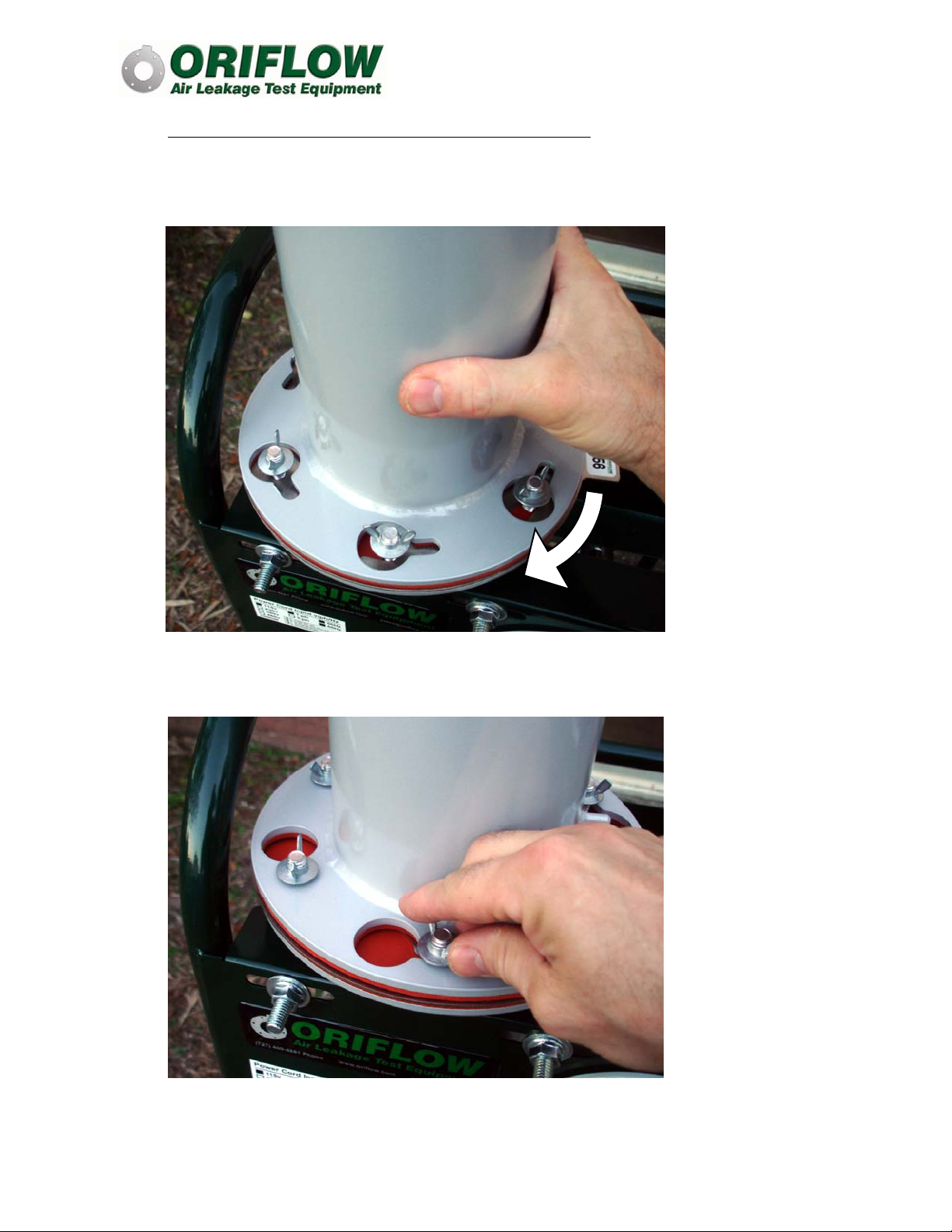
bolt/wing nut set, rotate clockwise, and tighten wing nuts (Figures 3 and 4).
Figure 3 – Install Upper Tube Section and Rotate Clockwise
Figure 4 – Tighten Wing Nuts after Rotation
Table des matières
Autres manuels Oriflow Équipement de test


Manuels Équipement de test populaires d'autres marques

SMART
SMART KANAAD SBT XTREME 3G Series Manuel utilisateur

Agilent Technologies
Agilent Technologies BERT Serial Manuel utilisateur

Agilent Technologies
Agilent Technologies N3280A Manuel utilisateur

Vernier
Vernier Go Direct Voltage Manuel utilisateur

Lifeloc
Lifeloc R.A.D.A.R. Manuel utilisateur

Fluke
Fluke T5-600 Instructions d'utilisation et d'installation


