OPTOGAMA FTC Series Manuel utilisateur

!
MANUAL v3.3
FTC
FLAT-TOP
CONVERTER
FTC series
KEY for DISCOVERIES

Table of contents
Table of contents" #....................................................................................................................................2
1. Safety requirements" #...........................................................................................................................4
2. Operation principle" #.............................................................................................................................5
2.1.Features and advantages!..............................................................................................................................................5
2.2.Optical design!...............................................................................................................................................................5
2.3.Contrast improvement. Angle adjustment!.....................................................................................................................5
3. Product description" #............................................................................................................................6
3.1.Optical specifications!....................................................................................................................................................6
3.2.Mechanical specifications!.............................................................................................................................................6
3.3.Electronic specifications!................................................................................................................................................6
3.4.Conditions!....................................................................................................................................................................6
4. Measurements" #....................................................................................................................................7
4.1.Setup parameters!.........................................................................................................................................................7
4.2.Flat top mode (no expander after FTC)!..........................................................................................................................7
4.3.Gaussian beam mode!...................................................................................................................................................8
4.4.FTC with beam expander (2X)!.......................................................................................................................................9
4.5.FTC with beam expander (3X)!.....................................................................................................................................10
4.6.Focusing Flat Top beam (with 3X expander)!................................................................................................................11
5. Controller" #..........................................................................................................................................12
5.1.Interfaces, pinout!........................................................................................................................................................12
5.2.Voltage levels!..............................................................................................................................................................12
5.3.What’s in the box?!......................................................................................................................................................12
5.4.Available accessories!..................................................................................................................................................12
6. Software" #...........................................................................................................................................13
6.1.Minimum Hardware requirements (recommended)!......................................................................................................13
6.2.System requirements!..................................................................................................................................................13
6.3.Supported client operating systems!............................................................................................................................13
6.4.Installing the software!.................................................................................................................................................13
6.5.Using the software!......................................................................................................................................................15
6.5.1.Connection!............................................................................................................................................................15
6.5.2.Settings, calibration!................................................................................................................................................15
6.5.3.Main window!..........................................................................................................................................................16
6.6.Updating the firmware!................................................................................................................................................17
4. Commands" #......................................................................................................................................18
4.1.Interface!.....................................................................................................................................................................18
4.2.Description!.................................................................................................................................................................18
5. Troubleshooting" #................................................................................................................................21
5.1.STATUS bits explanation!.............................................................................................................................................21
5.2.Serial communication example in Python!....................................................................................................................22
6. Technical information" #.......................................................................................................................23
6.1.FTC drawings!.............................................................................................................................................................23
6.2.Power supply!..............................................................................................................................................................24
2

FTC
Integrated Flat-Top beam converter
Congratulations on your purchase of the motorised laser
power attenuator from Optogama, UAB.
***
March 2022
Copyright UAB Optogama. All rights reserved.
No part of this manual may be reproduced, transmitted in
any form without the permission of Optogama.
Claims will not be accepted and warranty repair will not be
carried out in case of improper use, incorrect service and
maintenance not according to product instructions.
Warranty claim shall not be accepted if there are any signs
of:
•Non-authorised alteration
•Disassembling of the device
•Mechanical or any external damage
•If warranty term has expired
•Serial number of the product is missing
Symbols#
CAUTION!
Sections marked with this symbol indicate dangerous
situations that can result in damage to the device,
components connected to it or operator.
NOTE:
Sections marked with this symbol indicate important
information on laser power attenuator or about this manual.
Due to constant development of our products we reserve
the right to make changes in the production line without
further notice. Up-to-date information is available at our
website www.optogama.com. If there are any further
questions, please contact us.
Optogama is not liable for damage or injury resulting directly
or indirectly from use of this product for anything other than
its intended purpose.
The motorised laser power attenuator is intended for
industrial and scientific use only. If there are any other
electrical devices connected to or used in conjunction with
the laser power attenuator, all legal regulations and technical
standards that are applied to those devices must be
observed as well.
For any technical assistance and consultation please
3

1. Safety requirements#
•All safety instructions must be followed.
•All rules and regulations concerning the safe operation of
lasers must be known and applied while installing and
operating motorised laser power attenuator.
•Even when wearing safety glasses avoid eye contact
with direct or scattered laser light while assembling,
installing and operating the device.
•The device should never be exposed to dirt, dust or
moisture.
•Before any operation make sure the device is installed
correctly and well adjusted and all cover stickers are
removed.
•Protective measures should be considered if necessary.
•Electrical safety requirements must be complied while
operating this device.
CAUTION! High laser output power may damage or destroy
optical elements.
CAUTION! The device is meant to be used with a
collimated beam. Users take full responsibility when using
the device with a highly converging beam.
CAUTION! Before increasing laser power make sure the
device is aligned and there is no beam cut. It may damage
optical elements.
4
OUTPUT$
P-pol
INPUT
COVER STICKERS MUST $
BE REMOVED BEFORE USE
!
!
REFLECTED
BEAM$
S-pol

2. Operation principle#
FTC consists of quarter-order waveplate, polarising element
and Brewster type thin film polariser. Linear polarised laser
beam is converted to circular polarised by Quarter-order
waveplate. Brewster type thin polariser passes P-polarised
and reflects the S-polarised laser beam. Switching between
Flat-top and Gaussian beam mode is achieved by motorised
rotating of the polarising element, which is located in the
incident of the laser beam.
NOTE: Before use calibration is required
NOTE: Homing is required.
CAUTION! Before increasing laser power make sure the
device is aligned and there is no beam cut. It may damage
optical elements.
2.1. Features and advantages#
• Quick change between Gaussian and Flat-top beam
• The beam profile remains Flat-Top shape along optical
axis up to 1m*#
• Integrated controller
• Designed according your laser specs.
• Clear aperture up to 15 mm#
• Quick switching time - 0.2 sec
• High damage threshold up to 10J/cm2 (10 ns @ 1064
nm)
• Conversion efficiency up to 70% (while on Flat-Top
mode)
2.2. Optical design#
FTC optical elements are coated for high LIDT (10 (J/cm2)
(10 ns @ 1064 nm) and can be applied for high power
lasers. Manual rotation of quarter wave-plate should be
done once and remain in the same position for both -
Gaussian and Flat top beam modes. Switching is achieved
by motorised rotation of polarising element.
Fig 1. Schematic explanation of optical design of Flat-top converter (FTC)
2.3. Contrast improvement. Angle
adjustment#
Incident light’s angle αshould be adjusted to improve device
contrast (± 2 deg maximum). Use HEX 1,5 key.
• Clock-wise to decrease angle
• Counter clock-wise to increase angle
Fig 2. Schematic explanation of optical design of (FTC)
S - polarised
P - polarised
Quarter
waveplate
Brewster type
polariser
Input
Output
Polarising
element
Motorised
rotation
Manual
rotation
5

3. Product description#
Flat top converter unit is all in one motorised solution for a
Gaussian beam transformation to a Flat-Top (Top Hat)
beam. The beam profile remains Flat-Top shape along
optical axis up to 1 meter.
The device consist of quartz wave-plate, space-variant
wave-plate and a high contrast polariser.
The FTC is produced in the UV, visible and NIR spectral
ranges, from 250 nm to 2000 nm.
All optical components of the FTC are made for high LIDT
and provide stable and reliable performance even using
them with high power lasers in industrial applications.
A secondary laser beam from Flat top converter unit can be
rejected to an external beam dump. The beam dump is
used for avoiding any thermal effects or stress in the
housing of the FTC device.
3.1. Optical specifications#
3.2. Mechanical specifications#
3.3.Electronic specifications#
3.4. Conditions#
Clear input aperture
Up to ø15 mm
(depends on configuration)
Clear output aperture
Up to ø15 mm
(depends on configuration)
Conversion efficiency
and Transmission
Up to 70 % (Flat-Top beam mode)
No less than 97 %
(Gaussian beam mode)
LIDT coating
>10 [J/cm2] (10 ns @ 1064 nm)
Switching time
0.2 sec
Aboslute pos. encoder
Yes, with 3.7 arcsec resolution
Flat-Top beam
The beam profile remains Flat-Top
shape along optical axis up to:
- 0.5 meter
- 1 meter (when using beam expander)
Available coatings
A. Standard wavelenghts, nm
1st harm
2nd harm
3rd harm
1064
532
355
1020 - 1040
510 - 520
343
760-840
390 - 410
-
B. Custom wavelenghts
Custom coating available
FTC
FTC with $
beam dump (BD-6)
Lenght
105 mm
105 mm
Width
53 mm
70 mm
Height
62.5 mm
62.5 mm
Interface options:
Terminal
Using commands described
in p. 12 “Commands”
Software
Using LPA software
Input voltage
DC 12 V
Transmission speed
up to 115,200 bits/s (RS-232)
full speed USB 2.0
Operating temperature
10 0C to 40 0C
Storage temperature
-15 0C to 50 0C
6

4. Measurements#
4.1. Setup parameters#
$
Laser parameters:#
Wavelength 1064nm
Beam diameter X 4.2mm, Y 3.8mm 1/e2
Flat top converter parameters:#
Wavelength 1064nm
Beam diameter 4mm 1/e2
4.2. Flat top mode (no expander after FTC)#
Z=0cm
Z=10cm
Z=20cm
Z=30cm
Z=40cm
Z=50cm
Z - distance between Flat Top Converter and CMOS camera
7
Laser source$
1064nm
Beam
expander
CCD
FTC$
4mm 1/e2$
@1064
Z

4.3. Gaussian beam mode#
Z=0cm
Z=10cm
Z=20cm
Z=30cm
Z=40cm
Z=50cm
Z - distance between Flat Top Converter and CMOS camera
8

4.4. FTC with beam expander (2X)#
Laser source$
1064nm
Beam
expander
CCD
Beam
expande
r
FTC$
4mm 1/e2$
@1064
Z
Z=10cm
Z=20cm
Z=30cm
Z=40cm
Z=50cm
Z=75cm
Z=100cm
Z - distance between Flat Top Converter and CMOS camera
9
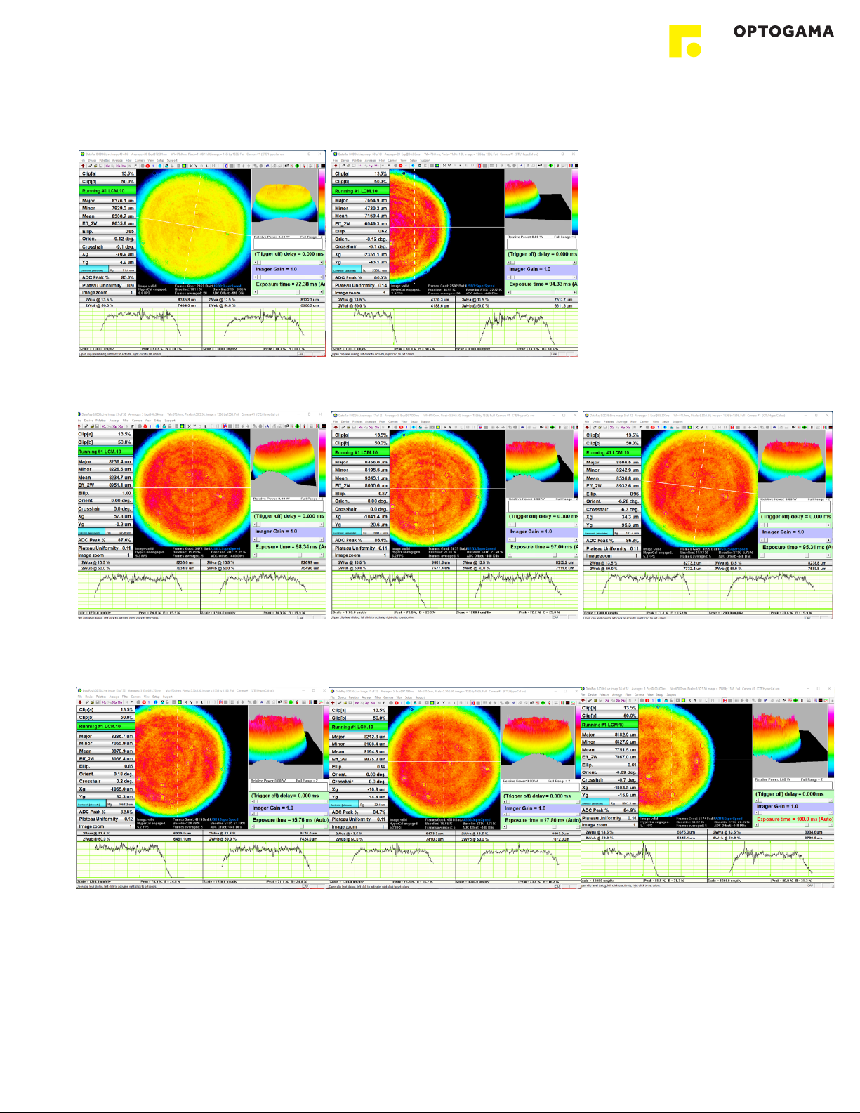
4.5. FTC with beam expander (3X)#
Z=10cm
Z=10cm (edge)
Z=30cm
Z=30cm (edge)
Z=50cm
Z=50cm (edge)
Z=100cm
Z=100cm (edge)
Z - distance between Flat Top Converter and CMOS camera
10
Table des matières


