Optimum BF20 L Vario Guide rapide

OPTIMUM
MASCHINEN - GERMANY
5. Dezember 2007 Page 1Recirculating ball screw assembly and maintenance instruction ; Version 2.0
© 2007
GB
Assembly and maintenance instruction
Version 2.0
BF20/ BF20L
Recirculating ball screw
Keep for future reference!

Assembly and maintenance instruction recirculating ball
OPTIMUM
MASCHINEN - GERMANY
5. Dezember 2007Page 2 Recirculating ball screw assembly and maintenance instruction ; Version 2.0
© 2007 GB
1 Assembly and maintenance instruction
recirculating ball screw
Recirculating ball screw
The delivery of the ball screw nut and spindle is performed corrosion-proof and
ready-for-assembly.
The ball-type linear are precision parts and need to be treated with outmost cleanliness and
care.
Please unpack the ball screw spindle directly before assembling.
1.1 Installation with spindle
The ball screw spindle needs to be installed radial and stressfree: While tightening the bea-
rings, you need to move the slide to and fro on the corresponding side.
1.2 Lubricating notes
General notes
Please consider the used lubricant as another machine element. Beside the careful design of
the ball-type linear drives the lubricant is mainly required to achieve the technically possible ser-
vice life.
For most applications, the lubricant is a wearing part and needs to be added accordingly.
As a matter of principle, a ball-type linear drive cannot be perfectly sealed, since there are
always parts of the running path which back out of the protected area. This way, dust and other
soilings of the environment are taken up which adhere to the greasy surfaces and provide for
additional lubricant consumption. A part of the soilings get into the nut and make the lubricant
thicken. Thus, the serviceability of the lubricant is decreasing which needs to be compensated
by the lubricating.
Before commissioning the spindle imperatively lubricate the whole length of the threadwith the
help of the nut.
Due to the axial movements between the nut and the spindle the loss of lubricant is higher than
for rolling bearings. Therefore, it is not possible to perform a lifetime lubrication.
Lubricating
In order to maintain the functional capability of the ball screws, they need to be lubricated suf-
ficiently. You may use the same lubricants as for rolling bearings. Lubricants containing MoS2 or
graphite must not be used. The choice of the lubricant and the kind of application can generally
be adapted to the lubrication of the other machine components. According to experience, a sin-
gle lifetime lubrication of the ball-type linear drives is not sufficient since the spindle always
discharges small amounts of lubricants off the nut.
Greasing
Use greases with EP additions (KP2K, DIN 51825). The regreasing interval is depending on the
environmental conditions. Generally, it is necessary to regrease every 200 to 600 operating
hours (about 3 months). It applies as standard value for the regreasing quantity: per each 1 cm
spindle diameter 1 cm³ grease per nut. Only use greases of the same saponification basis when
regreasing. If you use any greases of another saponification basis, it is necessary to clean the
recirculating ball screw and the spindle nut.
When you have regreased once, you should move the slide completely to and fro in order to
make sure that the grease will be uniformly spread over the ball screw spindle and in the nut.
Then you should regrease once again.

OPTIMUM
MASCHINEN - GERMANY
Assembly and maintenance instruction recirculating ball screw
5. Dezember 2007 Page 3Recirculating ball screw assembly and maintenance instruction ; Version 2.0
© 2007
GB
1.2.1 Greases
This list is a recommendation without engagement.
1.3 Notes regarding the storage
Ball-type linear drives are susceptible to damages and soiling. They need to be stored at a dry
place. The spindle needs to be supported in a way that it cannot bend.
Protect the lubricated ball-linear drive from dust and chips.
1.4 Technical data
Lubricant Classification Quality Manufacturer / Type Quan-
tity
Multi-purpose
grease on mineral
oil basis NLGI 3 K2K according to
DIN 51825
Aral
Multi-purpose grease HL3
2-3 cm³
Fuchs
Multi-purpose grease
FWA 220
BP
Energr. LS3
Shell
Retinax A
Alvania R3
Klüber
Isoflex NBU 15
Optimol
Optitemp TT1
Recirculating ball
screw Pitch Tolerance class Tolerance of deviation about 300 mm
travel
X-axis 4
IT7 52 µmY-axis 4
Z-axis 5

Assembly and maintenance instruction recirculating ball
OPTIMUM
MASCHINEN - GERMANY
5. Dezember 2007Page 4 Recirculating ball screw assembly and maintenance instruction ; Version 2.0
© 2007 GB
1.5 Packliste - Packing list
Nr.
No Achse
Axis Bezeichnung
Designation Artikelnummer
Item No Abbildung
Illustration Stck.
pc.
1Z - Achse
Z - axis Spindel (458 mm)
Spindle (458 mm) 3574302 1
2
Y - Achse
Y - axis Spindel (350 mm)
Spindle (350 mm)
3574301
1
Montagehülse
Mounting sleeve 1
3BF 20
X - Achse
X - axis Spindel (586 mm)
Spindle (586 mm) 3574303 1
4BF 20 L
X - Achse
X - axis Spindel (788 mm)
Spindle (788 mm) 3574304 1
5Schraubensatz
Screw set 3574305 Innensechskantschraube
Hex. socket head screw
DIN EN ISO 4762-M6x25 2
6Schraubensatz
Screw set 3574306 Linsenkopfschraube
Lens head screw
DIN EN ISO 7045-M6x12 4
7Schraubensatz
Screw set 3574307 Innensechskantschraube
Hex. socket head screw
DIN EN ISO 4762-M8x30 3
8Schraubensatz
Screw set 3574308 Innensechskantschraube
Hex. socket head screw
DIN EN ISO 4762-M8x50 2
9Schraubensatz
Screw set 3574309 Innensechskantschraube
Hex. socket head screw
DIN EN ISO 4762-M3x35 1
10 Montagesatz
X-, Y-, Z-Achse 3574356 1

OPTIMUM
MASCHINEN - GERMANY
Assembly and maintenance instruction recirculating ball screw
5. Dezember 2007 Page 5Recirculating ball screw assembly and maintenance instruction ; Version 2.0
© 2007
GB
1.6 Converting to a recirculating ball screw
INFORMATION
When assembling the BF20 and BF20L from trapezoidal threads to recirculating ball screws, it is
possible that the travels of the X-, Y- and Z-axis are changing.
1.6.1 Disassembly X-axis
£Start disassembling on the left side
of the drilling-milling machine.
£Unscrew the hexagon nut from the
spindle.
Fig.1-1: Handwheel left
£Remove the handwheel, if neces-
sary strike with a plastic tip hammer.
Fig.1-2: Handwheel left
£For CNC conversion disassemble
the step motor as well as the belt
pulleys, the housing and the belts
(CNC conversion instructions) at the
left side of the X-axis.
Fig.1-3: Disassemble step motor or housing
Unscrew hexagon
nut X-axis
Disassemble
handwheel X-axis
Housing
Step motor
Belts

Assembly and maintenance instruction recirculating ball
OPTIMUM
MASCHINEN - GERMANY
5. Dezember 2007Page 6 Recirculating ball screw assembly and maintenance instruction ; Version 2.0
© 2007 GB
£Loosen and unscrew hexagon nut,
then disassemble the toothed wheel.
Fig.1-4: Loosen nut
Fig.1-5: Disassemble toothed wheel
£Disassemble the two screws on the
left side of the X-axis.
Fig.1-6: Disassemble screws
Hexagon nut
Toothed wheel
Pillow block
Screws

OPTIMUM
MASCHINEN - GERMANY
Assembly and maintenance instruction recirculating ball screw
5. Dezember 2007 Page 7Recirculating ball screw assembly and maintenance instruction ; Version 2.0
© 2007
GB
£Drag the feather key from the
spindle.
Fig.1-7: Disassemble feather key
£Remove pillow block, if necessary
strike with a plastic tip hammer.
Fig.1-8: Disassemble pillow block
£Disassemble limit stops of the X-
axis.
Fig.1-9: Disassemble limit stop
Feather key
Pillow block
Limit stops

Assembly and maintenance instruction recirculating ball
OPTIMUM
MASCHINEN - GERMANY
5. Dezember 2007Page 8 Recirculating ball screw assembly and maintenance instruction ; Version 2.0
© 2007 GB
£Unscrew the indicator and the two
clamping levers of the X-axis.
Fig.1-10: Unscrew indicator and clamping
lever
£Now disassemble the right side of
the X-axis.
£Unscrew the hexagon nut from the
spindle.
Fig.1-11: Handwheel right
£Remove the handwheel, if neces-
sary strike with a plastic tip hammer.
Fig.1-12: Handwheel right
£Disassemble the two screws on the
right side of the X-axis.
Fig.1-13: Disassemble screws
Indicator
Clamping lever
Unscrew the
hexagon nut from
the X-axis
Disassemble hand-
wheel of the X-axis
Covering plate
Screws

OPTIMUM
MASCHINEN - GERMANY
Assembly and maintenance instruction recirculating ball screw
5. Dezember 2007 Page 9Recirculating ball screw assembly and maintenance instruction ; Version 2.0
© 2007
GB
£Drag the feather key from the
spindle.
Fig.1-14: Disassemble feather key
£Remove pillow block, if necessary
strike with a plastic tip hammer.
Fig.1-15: Disassemble pillow block
£Loosen the V-ledge at the locking
screw.
Fig.1-16: Loosen V-ledge
Feather key
Pillow block
Locking screw
Assembly and maintenance instruction recirculating ball
OPTIMUM
MASCHINEN - GERMANY
5. Dezember 2007Page 10 Recirculating ball screw assembly and maintenance instruction ; Version 2.0
© 2007 GB
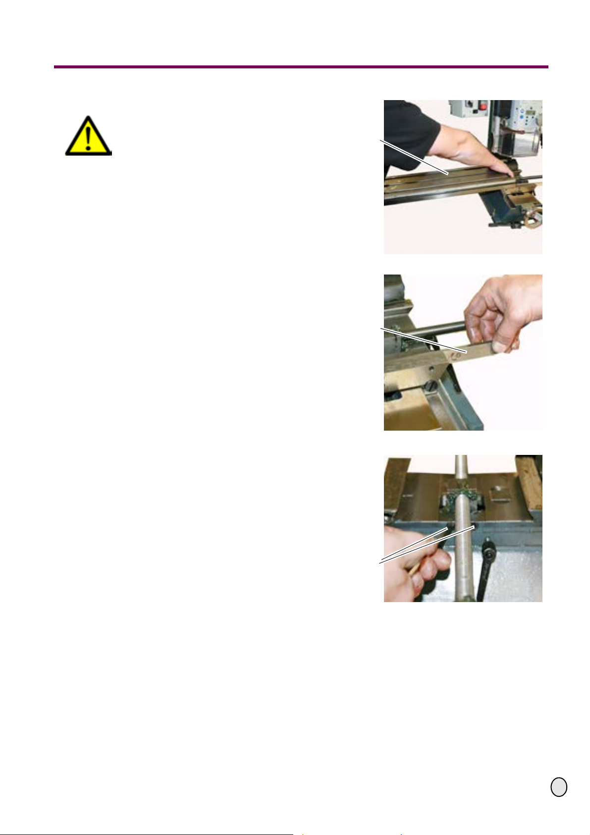
£Drag the table (X-axis) off-centre.
CAUTION!
Risk of crushing when dragging the
table. The table is very heavy!
If required, support the table from
the bottom when disassembling and
secure it against falling down.
Fig.1-17: Drag table (X-axis)
£Remove locking screw.
£Drag V-ledge out of the cross table.
Fig.1-18: Drag V-ledge
£Loosen the two hexagon socket
screws at the cross table.
Fig.1-19: Disassemble hexagon socket
screws
Table (X-axis)
V-ledge
Hexagon socket
screws
Autres manuels pour BF20 L Vario
1
Ce manuel convient aux modèles suivants
1
Table des matières
Autres manuels Optimum Outils


