opticis IPVDS-500-ED Manuel utilisateur

- 1 -
4K HDMI IP Video Wall Controller, IPVDS-500-ED
User Manual
Doc No. : OIPVDS-171123E / Rev1.3
WWW.OPTICIS.COM

- 2 -
Table of contents
1. Product Description ..................................................................................................4
1.1 Main Features ....................................................................................................5
1.2 Supporting Video Resolution for Input/Output .........................................5
2. Shipping Group ..........................................................................................................6
3. System Requirement .................................................................................................7
4. Exterior Description ...................................................................................................8
5. Installation ..................................................................................................................9
5.1 Hardware Installation Procedure ...................................................................9
5.2 Reset and Factory Reset ................................................................................10
5.3 PC Program Installation ................................................................................10
6. Start IPVDS-500-ED .................................................................................................11
6.1 Log-in ................................................................................................................11
6.2 Menu Contents ................................................................................................12
6.2.1 Application Icon Menu ........................................................................12
6.2.2 Ribbon Menu .........................................................................................12
6.3 Layout Management ......................................................................................16
6.3.1 Layout Editing ........................................................................................17
Zoom in/out
Audio Setup
6.3.2 Preset Save .............................................................................................19
6.4 Display Placement ..........................................................................................21
6.4.1 Display Layout Edit ...............................................................................22
Display Rotation
OSD
7. Context Menu ...........................................................................................................27

- 3 -
7.1 Layout Management Context Menu ...........................................................27
7.1.1 Encoder List Context Menu …....……………………………….………….27
Device Setup
Firmware Update
Set Source Name
Encoder Crop Feature
7.1.2 Video Wall Context Menu…………………………………………………...31
Remove Encoder
Split Merged Cell
Add Black Mask
Bring/Send Layer
Set Location Name
Delete Location Name
7.2 Display Placement Context Menu ...............................................................35
7.2.1 Decoder List Context Menu ................................................................35
Device Setup
Firmware Update
7.2.2 Video Wall Context Menu ...................................................................36
Remove Decoder
Decoder Layout Setup(Display Setup)
Bezel/Resolution/Stretch Type
8. Additional Feature ...................................................................................................39
8.1 Scheduling Feature .........................................................................................39
8.2 Multiple Video Wall ........................................................................................42
8.3 Plug-in Feature ................................................................................................46
9. Product Specification ..............................................................................................47
10. Troubleshooting .....................................................................................................48
11. Warranty ..................................................................................................................50

- 4 -
1. Product Description
IPVDS-500-ED, 4K HDMI IP Video Wall Controller, is an integrated control solution that plays
multi-source of audio/video (such as PC, Media player, DVD, or Blu-ray) on the video wall system
and multiple individual displays simutaneously.
This solution offers advanced video/audio matrix feature as well as control of video wall system
which divide high quality video source(4K30Hz or 1080p60Hz) into multiple video walls with using
IPVDS-500-E(encoder) and IPVDS-500-D(decoder) on IP network. IPVDS-500 enables convenient
system configuration and control for AV system integrator and installer, and cost-efficiency
compared to complicated matrix system. For these reasons, solution using IPVDS-500-ED provides
optimal soltion not only to large video wall system like control room, security, traffic control
system, but also to general venues like conference room, classroom, presentation room, and
worship service.
Program provided for system control offers preview function for source devices, and various
display configuration like merging, overlaying, clearing of displays on the layout management
with allocating audio/video sources with drag and drop operation of mouse.
Figure 1. Connection Diagram

- 5 -
1.1 Main Features
-TCP/IP based IP network: Gigabit Ethernet
-Up to 4K resolution (3840x2160 at 30Hz) or 1080p at 60Hz.
-Up to 256 displays (16x16, 4x64, 1x256 and etc) Video wall and multi-source support
-Supports analog/HDMI audio input and output
-Fast switching time / Low video latency
-Transmit HDMI/DVI video, USB, RS-232, Audio, DIO signal vid IP network
-Provides HDMI loop-thru port for Local display
-Provides merge, overlay and split features on Layout Management
-Support preset mode for user defined layout (save/load)
-Provides scheduling action with preset function (sequential/weekly mode)
-M:N virtual matrix supported
-Provides mounting bracket (model: OPSCB): VESA 75,100 standard (optional)
-Provides 1U rack, 4 in 1 rack & Power rack, PR5V-16: 16* 5V output (optional)
IPVDS-500 Control PC Application
-PC application for controlling Video wall and individual displays
-Provides drag and drop operation for host allocation and preview
-Provide allocate, merge, split, overlay function on Layout Management
-Provides preview screen before applying it to actual displays
-Provide total of 99 pre-sets for user defined layout (save/load)
-Provides pre-set scheduling function in Sequential (dwell time based) / Weekly mode (hourly/weekly based)
-Bezel compensation in 0.1mm unit
Figure 2. PC Application
-Application
Control Room / Traffic Control System / Security and Education / Digital Signage / Pro AV Field
1.2 Supporting Video Resolution for Input / Output
1) Supports HDMI 1.4, 3840x2160p/24/25/30Hz
2) Supports HDMI 1.4/HDTV, 1920x1080p60Hz
3) Supports VESA digital, 1920x1200p60Hz

- 6 -
2. Shipping Group
□IPVDS-500-ED □Power Adapter □HDMI cable 1.2m □Mini-USB cable □User Manual
2.1 General Specification
-IPVDS-500-E: TX (Encoder) or IPVDS-500-D: RX (Decoder)
-AC / DC power adaptor: One (1) unit of 5V / 2A
-One (1) HDMI male to male cable (1.2m)
-One (1) Mini-USB Cable for PC
-User manual
2.2 Optional Specification
-RS-232 cable: DB-9 male to 3pin terminal block
-Mounting bracket (OPSCB) complying with VESA 75, 100 standard
-1U rack (4 in 1 rack) and power rack (PR5V-16, 16*5V output)

- 7 -
3. System Requirement
3.1 Hardware Requirement
-Video source with HDMI output
-Display with HDMI input
-Support USB port of source when using HID feature
-No special requirement for memory size, CPU speed or chipset
3.2 Software Requirement
-No special requirement
3.3 Network Requirement
-L2/L3 Gigabit management Ethernet Switch is required for video matrix application to
apply correct operation.
-Below features are requirement for L2/L3 Gigabit management Ethernet Switch
1) Gigabit Ethernet
2) Jumbo frame (8K or more)
3) L3 : IGMP and multicasting protocol
4) L2 : IGMP snooping
Note: Although satisfaction of above requirement, some Network Switch might not
transmit video signal due to its performance.
-Please visit Opticis website or contact techsupp@opticis.com for technical support such
as bandwidth design, network topology and selection and setup of L2/L3 network switch
3.4 Control PC Requirement
-OS version check for video wall controlling PC application
-Requirement: Windows7 or higher
3.5 AC / DC Power Adapter
-IPVDS-500-ED is designed to use +5V AC/DC external power adapter

- 8 -
4. Exterior Description
4.1 IPVDS-500-E, Encoder
Figure. 3 Encoder Front Panel Figure. 4 Encoder Back Panel
USB IN : Connection with PC USB port for use of keyboard and mouse(HID)
L-IN : Line input port. Connection with line out audio
DIO / RS-232 : Optional
USB A: Connection of Keyboard / Mouse. (support F/W Upgrade)
Power Jack(5V, 3.5mm) : 5V DC power input
Reset : Reset button. (Factory reset when pressing more than 5 seconds)
HDMI IN (Source) : Video source input
Local Display (Monitor) : HDMI output for the local display
RJ-45 (LAN) : Connection with RJ-45 network cable (CAT5e / CAT6)
L/R/C Switch : TBD
4.2 IPVDS-500-D, Decoder
Figure. 5 Decoder Front Panel Figure. 6 Decoder Back Panel
L-OUT : Audio Line out port
DIO / RS-232 : Optional
Dual USB A :Connection of remote Keyboard / Mouse (F/W Upgrade support)
Power Jack(5V, 3.5mm) : 5V DC power input
Reset : Reset button. (Factory reset when pressing more than 5 seconds)
HDMI OUT : HDMI output for the display
RJ-45 (LAN) : Connection with RJ-45 network cable (CAT5e / CAT6)
Note1: If replacement of video source is needed, power reset of both encoder and decoder is
required as re-connecting +5V power adapter.

- 9 -
4.3 LED Indication
IPVDS-500-ED indicates power and network status with 2 LED on the front panel.
- Power status LED (RED)
‘Blinking’Booting, Initializing status
‘ON’Completion of booting, working status
- Link LED (Green)
‘Blinking’Ready to work with network connection, waiting for source status
‘ON’Connection with network link (encoder and decoder)
‘OFF’Disconnection with network link (encoder and decoder)
5. Installation
5.1 Hardware Installation Procedure
Important: Please follow below procedure. If not installed properly, it can suffer malfunction.
Step 1
Unpack the package.
Step 2
Turn on Source, Display, Network Switch (L2/L3).
Step 3
Turn on the PC for Video Wall control application and connect LAN cable (CAT5e / CAT6)
to network switch.
Step 4
Connect HDMI cable from display source to HDMI IN port of IPVDS-500-E (TX).
Step 5 (Optional)
Connect supplied USB cable in IPVDS-500-E (TX) to USB port in PC.
This step can be skipped if you don’t need local/remote control of keyboard and mouse.
Step 6 (Optional)
Connect HDMI cable from display output of HDMI monitor to IPVDS-500-E (TX).
Step 7
Connect LAN cable (CAT5e/6) from IPVDS-500-E (Tx) TO RJ45 port of network switch.

- 10 -
Step 8
Connect HDMI cable from IPVDS-500-D(RX) HDMI OUT port to Display. Then, connect
keyboard and mouse for remote control.
Important: IPVDS-500-D has to be connected to each of video wall displays in order. Refer
to display placement section for more detailed information.
Step 9
Connect LAN cable(CAT5e/6) from IPVDS-500-D(RX) to network switch.
Step 10
Plug +5V power adapters to both IPVDS-500-E(TX) and IPVDS-500-D(RX).
Note: Rebooting is mandatory for proper working if change of input source is needed.
5.2 Reset and Factory Reset
♦Reset: Device will reboot when reset button is pressed shortly
♦Factory Reset: Press and hold a reset button for approximately 5 seconds, then LED of
device will be turned OFF for factory reset after blinking
5.3 PC Application Installation
1) Download
(1) Visit Opticis website at www.opticis.com
(2) Click PRODUCTS > IP Video Wall / IPVDS-500-ED
(3) Download PC program (Password : 0315)
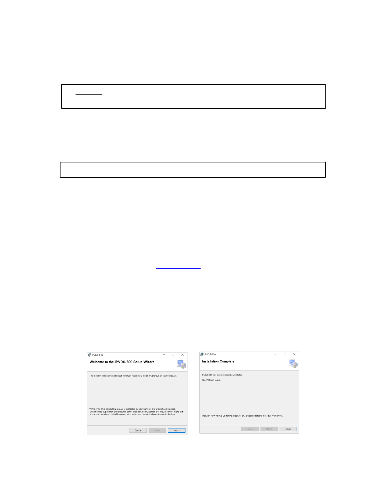
2) Installation
(1) Run setup.exe file in Windows operating system
(2) Follow on screen instruction
(3) Delete previous version of PC Application on the control panel of Windows OS,
before re-install or upgrade PC Application
Figure. 7 Application Installation
Autres manuels pour IPVDS-500-ED
1
Table des matières
Autres manuels opticis Contrôleurs