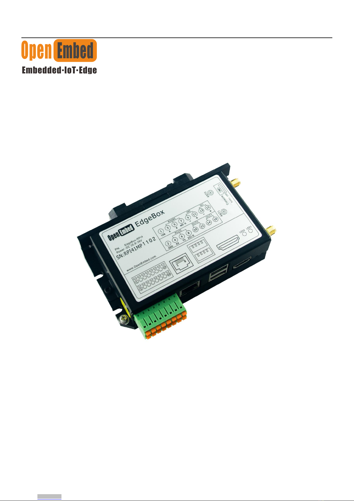
EdgeBox-RPI4 User Manual
www.OpenEmbed.com
Contents
1. Introduction....................................................................................................................................................................................... 4
1.1 Features...................................................................................................................................................................................4
1.2 Interfaces.................................................................................................................................................................................5
1.3 Block Diagram........................................................................................................................................................................7
2. Installation.........................................................................................................................................................................................8
2.1 Mounting.................................................................................................................................................................................8
2.2 Connectors and Interfaces.......................................................................................................................................................9
2.2.1 Power supply............................................................................................................................................................... 9
2.2.2 Serial Port (RS232 and RS485)...................................................................................................................................9
2.2.3 DI&DO...................................................................................................................................................................... 10
2.2.4 HDMI........................................................................................................................................................................ 11
2.2.5 Ethernet..................................................................................................................................................................... 11
2.2.6 USB HOST................................................................................................................................................................12
2.2.7 Console(USB typeC).................................................................................................................................................12
2.2.8 LED........................................................................................................................................................................... 12
2.2.9 SMA Connector
2.2.10 NANO SIM card slot...............................................................................................................................................14
2.2.11 Mini-PCIe................................................................................................................................................................ 15
2.2.12 M.2.......................................................................................................................................................................... 16
3. Drivers and Programming Interfaces.............................................................................................................................................. 17
3.1 LED.......................................................................................................................................................................................17
3.2 Serial Port (RS232 and RS485)............................................................................................................................................ 18
3.3 Cellular over Mini-PCIe....................................................................................................................................................... 18
3.4 WDT..................................................................................................................................................................................... 21
3.4.1 Block Diagram of WDT............................................................................................................................................ 21
3.4.2 How it works............................................................................................................................................................. 21
3.5 RTC.......................................................................................................................................................................................21
3.5.1.................................................................................................................................................................................... 21
3.5.2.................................................................................................................................................................................... 22
3.10 UPS for safe shut down...................................................................................................................................................... 22
4. Electrical specifications...................................................................................................................................................................24
4.1 Power consumption...............................................................................................................................................................24
4.2 UPS....................................................................................................................................................................................... 24
5. Mechanical Drawings......................................................................................................................................................................24
Downloaded from Arrow.com.Downloaded from Arrow.com.Downloaded from Arrow.com.