Omnitracs MCP50 Mode d’emploi

MCP50
Installation and
Troubleshooting
Guide
80-JB566-1 Rev. G
October 2015

Omnitracs, LLC
717 N. Harwood Street, Suite 1300
Dallas, TX 75201
U.S.A
Copyright © 2012-2015 Omnitracs, LLC. All rights reserved.
This technical data may be subject to U.S. and international export, re-export, or transfer ("export")
laws. Diversion contrary to U.S. and international law is strictly prohibited.
Omnitracs endeavors to ensure that the information in this document is correct and fairly stated, but
Omnitracs is not liable for any errors or omissions. Published information may not be up to date, and
it is important to confirm current status with Omnitracs.
Omnitracs is a trademark of Omnitracs, LLC. All other trademarks are the property of their respective
owners.
80-JB566-1 Rev. G
October 2015

80-JB566-1 Rev. G iii
MAY CONTAIN U.S. AND INTERNATIONAL EXPORT CONTROLLED INFORMATION
Installation Contents
1. Component Overview
2. Activation
3. Installation Planning
4. Vehicle Telematics Module 50 (VTM50) Installation
5. Antenna Installation
6. Display Interface Unit 50 (DIU50) Installation
7. Power/IO Cable Connection
8. Scanner
9. Optional Accessories
10. System Verification

Installation Contents
iv 80-JB566-1 Rev. G
MAY CONTAIN U.S. AND INTERNATIONAL EXPORT CONTROLLED INFORMATION

80-JB566-1 Rev. G v
MAY CONTAIN U.S. AND INTERNATIONAL EXPORT CONTROLLED INFORMATION
Important Safety Information Safety Definitions
Important Safety Information
Safety Definitions
The following Caution and Warning definitions are intended to advise the driver when it is
safe to use a display unit.
CAUTION indicates a potentially hazardous situation which, if not avoided, may result in
minor or moderate injury. It may also be used to alert against unsafe practices.
WARNING indicates a potentially hazardous situation which, if not avoided, could result in
death or serious injury.
Safety Advice
The following Safety Advice is provided for drivers, installers, and application developers who
use and/or locate all types of display units.
If you are a Driver, do not use a display unit when the vehicle is in motion.
If you are an Installer, do not locate the display unit, including third-party devices, where it
obstructs the driver’s field of vision, distracts the driver from the driving task, or interferes with
the driver’s operation of controls or instruments. The following is displayed when ignition is
turned on.
If you are a Third-party Device Manufacturer or Application Developer, it is your
responsibility to provide appropriate warnings regarding the safe use of your device(s) in
conjunction with Omnitracs equipment. Applications should not require the driver to divert his
attention from the road while driving a vehicle.

Safety Advice Important Safety Information
vi 80-JB566-1 Rev. G
MAY CONTAIN U.S. AND INTERNATIONAL EXPORT CONTROLLED INFORMATION

80-JB566-1 Rev. G 1-1
MAY CONTAIN U.S. AND INTERNATIONAL EXPORT CONTROLLED INFORMATION
Component Overview Components
1
Component Overview
Components
Antenna
The antenna includes a cellular modem and GPS receiver.
• Dimensions: 4 1/8 x 2 1/8 x 1 1/8 inches
• Weight:6 ounces
• Cable attached for connection to VTM
(cellular/GPS leads)
• Cable length: 7 feet
Display Interface Unit 50 (DIU50)
A color graphical display that integrates touchscreen functionality.
• Dimensions: 7 5/8 x 5 1/2 x 1 1/2 inches
• Weight: 1.2 pounds
• Screen size: 7-inch diagonal, resolution: 800 x 480
• Built-in speaker for text-to-speech
• USB 2.0 Host Port
• Cable attached for connection to VTM
• Cable length: 9 1/2 feet

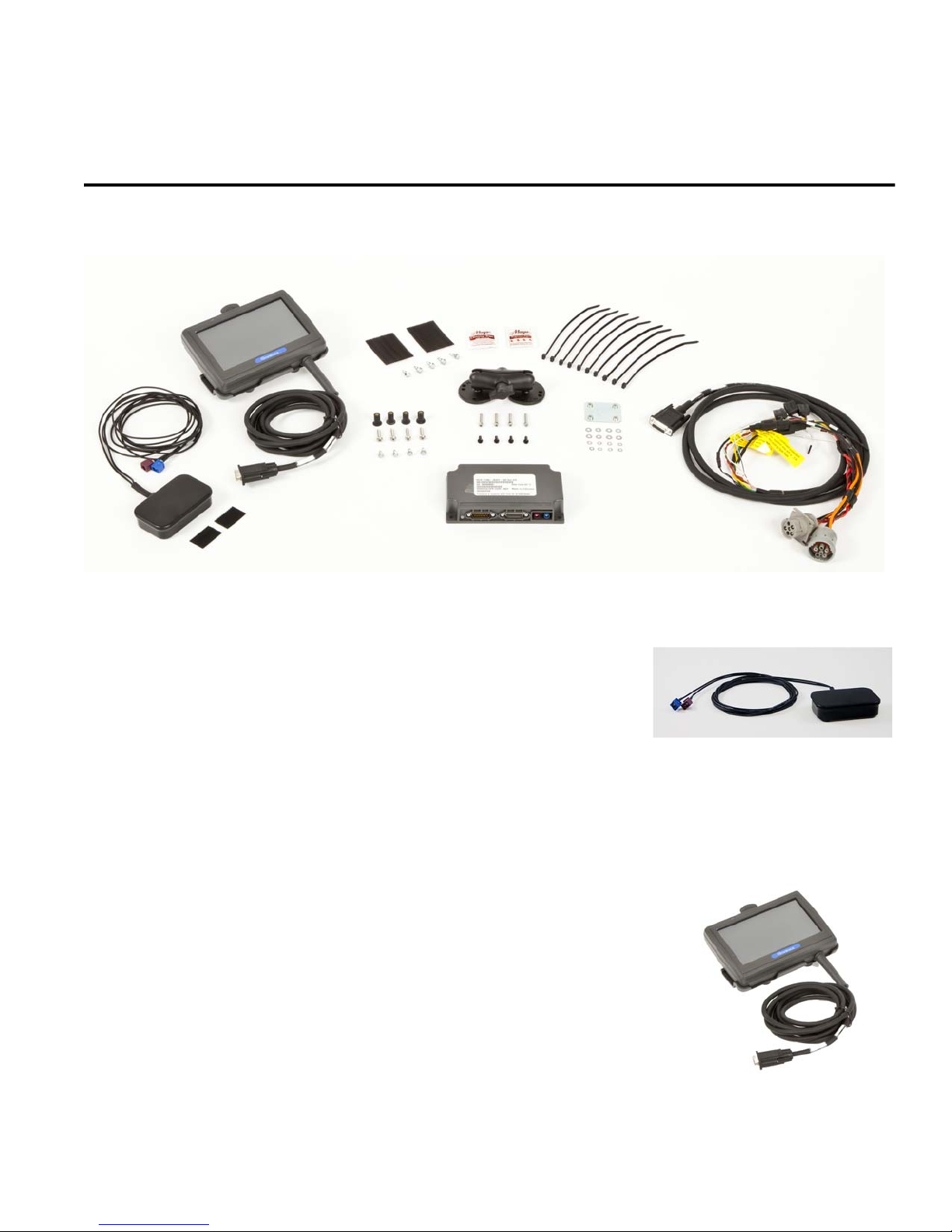
Vehicle Telematics Module 50 (VTM50) Component Overview
1-2 80-JB566-1 Rev. G
MAY CONTAIN U.S. AND INTERNATIONAL EXPORT CONTROLLED INFORMATION
Vehicle Telematics Module 50 (VTM50)
The VTM provides power to the display and processing
of vehicle data.
• Dimensions: 6 1/2 x 3 3/4 x 1 1/2 inches
• Weight: 12 ounces
• Supports J1587 and J1939 vehicle data protocols
• Accelerometer
Power/IO Cable (9-pin or 6-pin “Y” cable)
Connects to a truck’s 9-pin or 6-pin diagnostic connector for
power and vehicle data on J1587 and J1939 data links.
• Cable length: 7 feet
Volvo/Mack J1587/J1708 and J1939 250 Kbs
Volvo trucks 2014 or newer with Volvo engines and Mack
trucks 2014 or newer with Mack engines will use a diagnostic
connector that resembles a standard automotive OBDII
connector. This connector still contains the J1939/J1708
and does not use the OBDII protocol.
No separate ignition connection is necessary. The ignition
connection is part of the cable as it is available on the
connector for these trucks
Hino
For early 2011 Hino trucks, Power, Ground, Ignition, and J1939
are needed from the truck’s wiring in the dash and will require
butt splicing.
For late model 2011 and 2012 or newer Hino trucks, you can
connect directly to the Hino Telematics connector.
The blue connector is for Japanese manufactured trucks and
the white connector is for US manufactured trucks.
No separate ignition connection is necessary. The ignition
connection is part of the cable as it is available on the
connector for these trucks.

80-JB566-1 Rev. G 1-3
MAY CONTAIN U.S. AND INTERNATIONAL EXPORT CONTROLLED INFORMATION
Component Overview Display Holster
Display Holster
Allows the display to be moved around the cab, or secured
on the dash while the truck is operating.
RAM Mount
Used for mounting the display/holster to the dash.
Backing Plate
Always use the supplied backing plate to
strengthen the support for the mount.
Product Documentation
You should have also received the following product documentation. Ensure you leave all
documents in the cab of the vehicle.
• MCP50 Quick Reference Card (80-JB662-1)
• HOS DOT Quick Reference Card for use with the MCP50 (80-JB918-1)
• VIR DOT Quick Reference Card (80-JA348-1)
• MCP50 Getting Started Guide (80-JB107-1)

Product Documentation Component Overview
1-4 80-JB566-1 Rev. G
MAY CONTAIN U.S. AND INTERNATIONAL EXPORT CONTROLLED INFORMATION
Autres manuels pour MCP50
1
Table des matières


