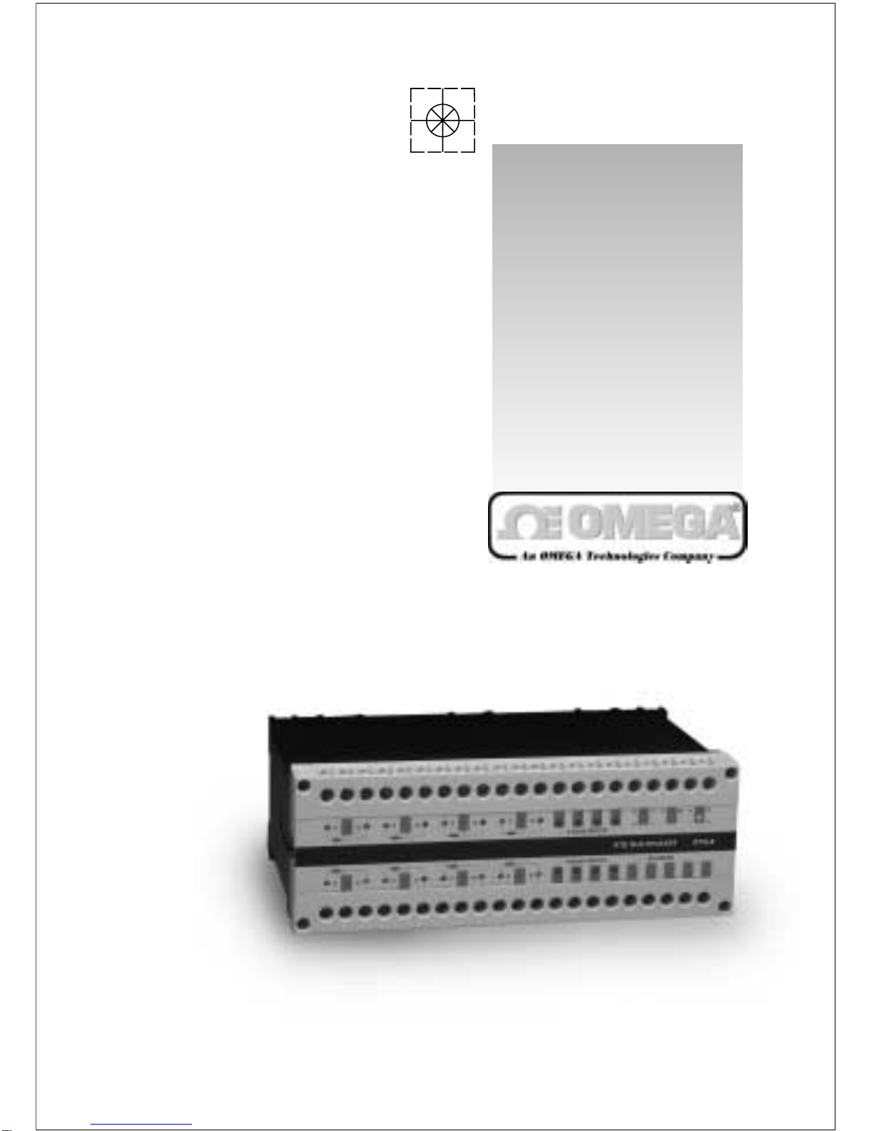
Omega DRA-RTM-8 Manuel utilisateur


USA and Canada: Sales Service: 1-800-826-6342 / 1-800-TC-OMEGASM
Customer Service: 1-800-622-2378 / 1-800-622-BESTSM
Engineering Service: 1-800-872-9436 / 1-800-USA-WHENS M
TELEX: 996404 EASYLINK: 62968934 CABLE: OMEGA
Mexico and
Latin America: Tel: (95) 800-TC-OMEGASM FAX: (95) 203-359-7807
Benelux: Postbus 8034, 1180 LAAmstelveen, The Netherlands
Tel: (31) 20 6418405 FAX: (31) 20 6434643
Toll Free in Benelux: 06 0993344
e-mail: [email protected]
Czech Republic: Ostravska 767,733 01 Karvina
Tel:42(69)6311899 FAX:42(69) 6311114
e-mail: [email protected]
France: 9, rue Denis Papin, 78190 Trappes
Tel: (33) 130-621-400 FAX: (33) 130-699-120
Toll Free in France: 0800-4-06342
e-mail: [email protected]
Germany/Austria: Daimlerstrasse 26, D-75392 Deckenpfronn, Germany
Tel: 49 (07056) 3017 FAX: 49 (07056) 8540
Toll Free in Germany: 0130 11 21 66
e-mail: [email protected]
United Kingdom: 25 Swannington Road, P.O. Box 7, Omega Drive,
ISO 9002 Certified Broughton Astley, Leicestershire, Irlam, Manchester,
LE9 6TU, England M44 5EX, England
Tel: 44 (1455) 285520 Tel: 44 (161) 777-6611
FAX: 44 (1455) 283912 FAX: 44 (161) 777-6622
Toll Free in England: 0800-488-488
e-mail: [email protected]
OMEGAnetSM On-Line Service
http://www.omega.com Internet e-mail
omega.com
TM
OMEGA
®
It is the policy of OMEGA to comply with all worldwide safety and EMC/EMI regulations that apply.
OMEGA is constantly pursuing certification of its products to the European New Approach Directives.
OMEGA will add the CE mark to every appropriate device upon certification.
The information contained in this document is believed to be correct but OMEGA Engineering, Inc.
accepts no liability for any errors it contains, and reserves the right to alter specifications without notice.
WARNING: These products are not designed for use in, and should not be used for, patient connected
applications.
One Omega Drive, Box 4047
Stamford, CT 06907-0047
Tel: (203) 359-1660
FAX: (203) 359-7700
e-mail: [email protected]
976 Bergar
Laval (Quebec) H7L 5A1
Tel: (514) 856-6928
FAX: (514) 856-6886
e-mail: [email protected]
USA:
ISO9001Certified Canada:

Contents
1. GENERAL DESCRIPTION
2. MOUNTING INSTRUCTIONS
3. REPLACING FUSES
4. ASSEMBLY
5. CURRENT INPUTS
6. CONNECTING TRANSMITTERS TO THE MULTIPLEXER
7. CONNECTING Pt-100 TO THE MULTIPLEXER
8. CONNECTING THE MULTIPLEXER TO A PLC
9. CONTROL
9.1 Enable
9.2 Address
9.3 Address Polarity
9.4 Control Tables
10. CALIBRATION
10.1 Calibration Procedure
10.2 Calibration Tables
10.2.1 "ZERO" - Coarse Calibration Tables
10.2.2 "SPAN" - Coarse Calibration Tables
11. MULTIDROP CONFIGURATION
12. SPECIFICATIONS
1

1. GENERAL DESCRIPTION
2
WARNING: Never install a fuse rated more than 800mA
The DRA-RTM-8 is a multiplexer for 16 analog inputs - eight of which, marked
1-8, are direct inputs for Pt-100 sensors, while the remaining (9-16), are for 4-
20mA current loops.
The DRA-RTM-8 output format is a 4-20mA current loop, with a 28mA limitation.
Each Pt-100 input has its own signal conditioner, allowing each input to be
calibrated separately. Each signal conditioner includes six DIP switches for coarse
calibration and two potentiometers for fine tuning.
2. MOUNTING INSTRUCTIONS
The DRA-RTM-8 is designed for standard DIN rail mounting.
Place the unit on the upper part of the mounting rail with the fastening tab facing
down. Using a suitable flat screwdriver loosen the tab slightly and attach the unit
to the rail. Once the tab is loosened, ensure that the unit is fastened securely in
place.
3. REPLACING FUSES
To replace a blown fuse, disassemble the unit as follows:
a. Take off both terminal strips by removing the four screws at the edges.
Note: This does not require disconnecting the cables connected to the strips.
b. Remove the front panel using a suitable flat screwdriver. Press down gently on
the plastic springloaded tabs located in the slots on either side of the unit.
c. Disconnect the flat connectors which connects the front panel printed circuit.
d. Replace the blown fuse.
4. ASSEMBLY
The DRA-RTM-8 unit includes two printed circuit cards designated as P.N 7020
and P.N 7021. The two printed circuit cards should occupy the slots in the
enclosure according to fig 1.

3
Insert the two printed cards into their slots.
Connect the flat cable between them.
Connect the front panel flat cables. The
panel must be inserted into the grooves on
both sides of the case while pressing down
until a distinct "click" is heard. Assembly is
completed by laying the terminal strips in
place.
Note: The terminal strips are polarized and must not be placed backwards.
5. CURRENT INPUTS
The eight 4-20mA current inputs are marked as channels 9-16. These inputs are
for current only. The "COM" input is the return for all the current channels. It is
possible to connect any current source, as long as a closed loop is maintained.
Figure 1.
6. CONNECTING TRANSMITTERS TO THE MULTIPLEXER
6.1 TWO WIRE TRANSMITTER
A Two-Wire transmitter is connected so that its
positive terminal is connected to the positive
terminal of the power supply, and its negative
terminal is connected to the "I" terminal.
(see fig 2) Figure 2.
6.2 FOUR WIRE TRANSMITTER
A Four-Wire transmitter is connected so that its
positive terminal is connected to the "I" terminal,
and its negative terminal is connected to the
"COM" terminal. (see fig 3)
Figure 3.
WARNING: Voltage sources should not be connected to the current
inputs,as permanent damage might occur.

4
Figure 4.
7. CONNECTING Pt-100 TO THE MULTIPLEXER
The Pt-100 probe should be connected according to fig 4. The
three wires connecting the probe should be identical.
The distance of the probe can be up to 200 meters.
A shielded cable is recommended.
The shield should be grounded at one point. When possible,
connect the ground at the multiplexer's end.
8. CONNECTING THE DRA-RTM-8 TO A PLC
The multiplexer output should be connected to 4-20mA input of the PLC analog
module (see fig 5).
The DRA-RTM-8 multiplexer generates the output current, therefore the PLC analog
module should be configured for four wire transmitter connection.
WARNING: NEVER apply 24Vdc to the DRA-RTM-8's +Io terminal
as in two-wire connection, and make sure that the PLC's
analog module is configured as a passive input.
9. CONTROL
The DRA-RTM-8 unit is controlled via four
address lines and one E (Enable) line.
The control terminals (Address and
Enable), were designed to receive control
signals from TTL levels up to 60V so that
almost any PLC's DC output module can
be used. (see fig 5)
Figure 5.
9.1 ENABLE
The unit is enabled when a logical "1" (5V < E < 60V) is connected to the E
Terminal. In a disabled state, the DRA-RTM-8 outputs no current and reflects a
Hi-Z state. This feature allows the connection of several DRA-RTM-8 units by tying
their outputs and control in parallel and addressing them by controlling the
individual Enable terminals.

5
9.2 ADDRESS
The required channel is selected by
four address lines.
The operating voltages are:
Logical "1" 5V < Vi < 60V
Logical "0" 0V < Vi< 0.5V
9.3 ADDRESS POLARITY (see fig 6)
Address polarity is controlled by three internal pins and a jumper over two of them,
located on PN 7021 printed circuit board, accessible behind the Enable terminal.
The unit is supplied with the jumper set for "true high" control logic, i.e. "0000"
selects channel #1, and "1111" selects channel #16.
Moving the jumper to the second alternative, reverses the logic.
Figure 6.
Note: If the address contros voltages are generated from different power
supplies, then its negative terminal should be connected to the
DRA-TM-8's "COM" terminal.
9.4 CONTROL TABLES
9.4.1 "TRUE LOW" SETTING
ADDRESS BUS EOUTPUT
CHANNEL
A0A1A2
A3
1
1
1
1
1
0
0
0
0
1
0
0
1
1
0
0
1
0
1
0
1
1
1
1
1
8
7
6
5
4
1
1
1
x
1
1
1
x
0
1
1
x
1
0
1
x
1
1
1
0
3
2
1
NO OUTPUT
ADDRESS BUS EOUTPUT
CHANNEL
A0A1A2
A3
0
0
0
0
0
0
0
0
0
1
0
0
1
1
0
0
1
0
1
0
1
1
1
1
1
16
15
14
13
12
0
0
0
x
1
1
1
x
0
1
1
x
1
0
1
x
1
1
1
0
11
10
9
NO OUTPUT

6
ADDRESS BUS E/T OUTPUT
CHANNEL
A0A1A2
A3
1
1
1
1
1
0
0
0
0
1
0
0
1
1
0
0
1
0
1
0
1
1
1
1
1
9
10
11
12
13
1
1
1
x
1
1
1
x
0
1
1
x
1
0
1
x
1
1
1
0
14
15
16
TEST MODE
ADDRESS BUS E/T OUTPUT
CHANNEL
A0A1A2
A3
0
0
0
0
0
0
0
0
0
1
0
0
1
1
0
0
1
0
1
0
1
1
1
1
1
1
2
3
4
5
0
0
0
x
1
1
1
x
0
1
1
x
1
0
1
x
1
1
1
0
6
7
8
TEST MODE
9.4.2 "TRUE HIGH" SETTING
Note: The unit includes three internal potentiometers. These potentiometers
are carefully adjusted and sealed in the factory. It is not recommended
to alter these calibration potentiometers.
10. CALIBRATION
To calibrate the DRA-RTM-8, the limits must be defined.
Tmin is the temperature at which the output current is 4mA.
Tmax is the temperature at which the output current is 20mA.
Tspan is the difference between Tmax and Tmin.
10.1 CALIBRATION PROCEDURE
a. Remove the terminal strips to get access to the coarse calibration switches.
b. Set the channels DIP switches to the desired calibration ranges according to the
calibration tables.
c. Re-install the terminals strips. The terminal strips are polarized and should be
returned to their original position.
d. Connect a Pt-100 calibrator* set for Tmin to the proper input terminals.
e. Apply the proper channel selection code by connecting those which according
the table should be "1" to the +PWR terminal.
f. Start calibrating by adjusting the proper "Z" potentiometer to obtain an output
current of 4.000mA.
g. Set the calibrator for Tmax and adjust the "S" potentiometer to obtain an output
current of 20.000mA.
h. Repeat this procedure until satisfactory results are obtained.

7
* The calibrator is set according to DIN 43760 Pt-100 table (a= 0.00385)
10.2 CALIBRATION TABLES
Note: Logic state of "0" is when the DIP switch lever is down.
10.2.1 "ZERO" - COARSE CALIBRATION TABLES
ZERO TEMP
O
CCHANNELS 1-4
SW5 SW4
SW6
-50.....10
8.....75
74...140
139...206
205...272
270...338
336...404
401...470
1
1
1
1
1
1
1
1
1
1
1
1
0
0
0
00
0
0
0
0
0
0
0
CHANNELS 5-8
SW2 SW3
SW1
1
1
1
1
1
1
1
1
1
1
1
1
0
0
0
00
0
0
0
0
0
0
0
10.2.2 "SPAN" - COARSE CALIBRATION TABLES
SPAN
O
CCHANNELS 1-4
SW2 SW3
SW1
50.....76
65...115
110...180
135...225
215...440
400...800
1
0
0
1
0
0
0
1
1
1
0
1
0
0
1
1
1
0
CHANNELS 5-8
SW5 SW4
SW6
1
0
0
1
0
0
0
1
1
1
0
1
0
0
1
1
1
0
i. Change the address to the next channel to be calibrated.
j. Repeat steps b to h

8
12. SPECIFICATIONS
11. MULTIDROP CONFIGURATION
In the disabled state (E=0), the multiplexer outputs no current and exhibits a high
Z state. This mode allows the connection of several DRA-RTM-8 units to one PLC's
analog input, by tying their output terminals and the address lines in parallel, and
applying individual Enable lines to select the desired multiplexer by disabling all
but one (see fig 7).
Figure 7.
ANALOG +
ANALOG -
PLC
ANALOG
INPUT
MODULE
ENABLE 1
DISCRETE
OUTPUT
MODULE
ENABLE 2
MSB
LSB
ANALOG INPUTS:
RTD INPUT:
Zero adjustability:
Span adjustability:
Lead Compensation Error:
Max Lead Resistance:
Pt-100 linearization:
CURRENT INPUT
Max Input Current:
Reverse Polarity Protection:
Output Accuracy (Refer to Current Input):
CONTROL INPUTS:
Logic:
Logic Levels:
OUTPUT:
SWITCHING TIME:
INDICATORS:
SUPPLY VOLTAGE:
SUPPLY CURRENT CONSUMPTION:
FUSE:
TEMPERATURE STABILITY:
OPERATING TEMPERATURE:
STORAGE TEMPERATURE:
HUMIDITY:
HOUSING:
Box:
Terminal:
WEIGHT:
DIMENSIONS:
8, Pt-100 Channels
a
=0.00385
8, 0/4-20mA Channels
50 to +200
o
C
50 to 750
o
C
0.025
o
C for 10
W
lead resistance
120
W
two ways
0.1% of span max.
30 mA
Yes
0.1% of span max.
4 Address
1 Enable input
True High or True Low (User selectable)
Low: "0" < 0.5V High: 5 < "1" < 60V
4-20mA, Current Loop
< 20
m
Sec (into a resistive load)
1 Yellow LED, Power-On indicator
8 Red LEDs, current activity indicators
24 10% Vdc (regulated)
120 mA 10mA
150 mA, Fast Blow (5x20mm)
0.01% of span/1
o
C
0 to 60
o
C (32 to 140
o
F)
-25 to +85
o
C (-13 to 185
o
F)
5 to 95% Relative humidity, non-condensing
Plastic Polycarbonate
According to IP50 DIN 40050
According to IP20 DIN 40050
0.9 Kg. (2.0 lb.)
73Hx200Wx121mmD (2.88"x7.88"x4.76")
Table des matières
Autres manuels Omega Multiplexeur
Manuels Multiplexeur populaires d'autres marques

ADTRAN
ADTRAN Frameport 768 Manuel utilisateur

Elo TouchSystems
Elo TouchSystems E247 Manuel utilisateur

Paradyne
Paradyne Hotwire 8786 Manuel utilisateur

RFL Electronics
RFL Electronics 9508D UCC Manuel utilisateur

Miranda
Miranda AMX-101i Mode d’emploi

ShipModul
ShipModul MiniPlex-AIX NMEA-0183 Manuel utilisateur