Olsberg MultiDrive 2 Manuel de la liste des pièces
English
Technical description
MultiDrive 2
Display Controller 8F
2012

2

3
Introduction
SAFETY PHILOSOPHY
The control system fulls stringent safety
requirements in terms of reliability and
operational safety.
The products are CE-marked and approved
in accordance with machinery directive
2006/42/EG.
The system conforms to ISO 13849-1:2006
category 3 PLd.
Olsbergs radio remote control system has been devel-
oped to provide operators with continual feedback via
its display whenever they activate a lever or button on
the hand controller. The hand controller’s standard
menu selection system utilises the display to provide
the operator with real time information about the
chosen menu, battery status, reception conditions etc.
The hand controller contains a two-way communication
radio enabling information to be sent both to it and from
it. The radio decoder contains a corresponding unit to
handle trac at the other end.
The hand controller utilises bluetooth radio and therefore
operates in the 2.4GHz band, which is a free band that
has been approved practically worldwide. This means
that no license is needed and the radio can in principle be
used everywhere including over national boundaries.
The side displays show the symbol for the function each
lever activates in the chosen menu. When the operator
changes menu, the symbols change to the functions that
become active.
The centre display provides information about which
menu has been chosen, as well as indicating the radio
reception conditions, battery status, fault information,
micro, manual extension and so on.

4
BatteryCable connector
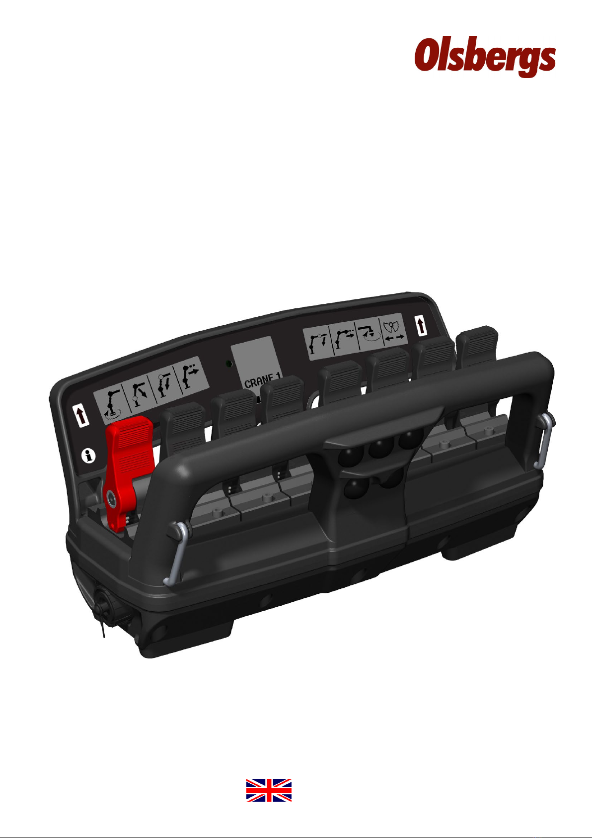
Controller
The hand controller is the device that the operator
uses to control his crane and his vehicle.
The hand controller has eight levers. The functions of
each lever may be the same or dierent in dierent
menus, however only one function can exist per lever
at any one time.
If a lever is faulty, or if it is deected on starting, it is
disabled. The other levers operate as usual.
Activating the micro-button enables the operator to set
the levers to 50% or 20% of normal speed thus enabling
the crane to be operated with increased precision.
Cable operation.
Flicker: 20Hz
Decoder on,
under initialisation.
Blink: 0,6s 1s 1s0,6s osv
Radio Decoder
The radio decoder contains one of the radio units.
The decoder translates the radio trac, consisting
of lever and button data from the hand controller,
to the CAN bus.
For safety reasons, it is extremely important that data
is not corrupted, therefor the decoder has dual micro-
processors which monitor each other to ensure accu-
racy in the translation. The controller and the decoder
must be “paired” with each other to establish a connec-
tion. A unique code is loaded and stored in each unit.
The pairing procedure is described elsewhere in this
documentation.
A relay box is normally mounted on the bottom
of the decoder. More information regarding
the relay box and its function is provided by
a separate brochure.
Blink mode for each LED in dierent operating cases:
Decoder powered,
no radio connection.
Radio connection present,
safety requirements not met.
Normal operation.
Internal error or failed
teach-in procedure.
Teach-in procedure in
progress.
Teach-in procedure
complete.
Blink: Steady:
Blink:
Steady:
Flicker:
Steady:
Steady:
0,6s 1s 1s0,6s etc 20Hz
0,6s 1s 1s0,6s etc
Flicker: 20Hz
CAN-bus
CAN-bus
LED L1:
Fault status
LED L2:
Radio commu-
nication status
LED L3:
Radio control on

5
Side display, left
”Twilight relay”
Side display, right
Centre display
Release
button
Info button for
showing error
codes in the
centre display
Stop button
Buttons for main menus
CRANE EXTRA ON-OFF
Horn Micro
Lever 1 to 8
(display symbol shows
direction of operation
with lever forward)

6
Figure 1
Figure 2
Figure 3
Getting started!
The procedure for starting the system is described below.
INSTALLING THE BATTERY
Install a fully-charged battery in the hand controller as
shown on the right. (Figure 1)
The battery must be installed correctly or the hand con-
troller will not start.
A fully-charged 1700mAh battery provides approximately
8 hours of operation.
ACTIVATING THE SYSTEM ON THE CRANE
To turn on the crane’s control unit press the on button
on the Power Display Box, PDB. The LED above the
button will then start to ash. (Figure 2)
Then press the remote control button on the PDB, the
LED above this button will light and stay on. (Figure 3)
The decoder starts when remote control operation is
selected and the decoder’s yellow LED starts to blinks.
The crane’s control unit is now ready to be connected
with the hand controller.
ACTIVATING THE CONTROLLER
To activate the hand controller pull the stop button out
by turning it clockwise. The hand controller is powered
up and starts to establish a radio link with the decoder
on the crane. While radio contact is being established a
ashing hourglass and the text “Wait” is shown on the
centre display. (Figure 4)
Remaining battery power is displayed and the signal
strength symbol ashes when radio communication is
established but the hand controller and decoder are still
exchanging connection data.
Connection time for a cold-start can be up to 5 seconds.
A cold-start occurs when the hand controller or decoder
on the crane have been o for the last 10 minutes. When
restarting within 10 minutes of turning o the hand
controller, the radio link is still established and the hand
controller is ready for use immediately.
The factory setting for the period of time the hand con-
troller maintains contact with the decoder after pressing
the stop button is 10 minutes.

7
Figure 4
Figure 5
Figure 7
Figure 6
RADIO LINK ESTABLISHED
When the radio connection is established the yellow
LED on the decoder shines steadily and the green
LED blinks rapidly. (Figure 5)
The hourglass symbol on the hand controller disap-
pears and the text “Wait” (Figure 4) is replaced by
“CRANE 1”. (Figure 7)
The radio signal strength is now shown without
blinking.
If the radio connection is disrupted for longer than
0.5 of a second, then “CRANE 1” is replaced by the
“RESTART” symbol and the signal strength symbol
will either disappears or start blinking. (Figure 6)
START MENU
If the hand controller has been turned o it will
always restart in “CRANE 1”. (Figure 7)
8
123456
CRANE EXTRA ON-OFF
Buttons for main menus
78
EXTRA
menu 2,3,4
CRANE
menu 1,2,3,4
ON-OFF
menu 1,2
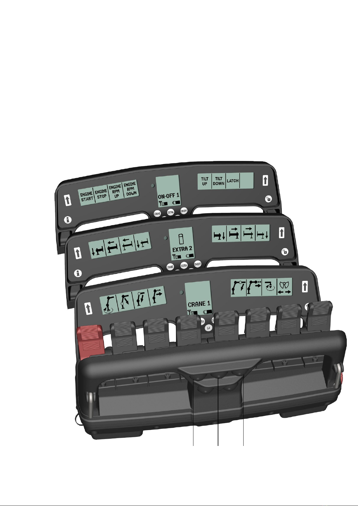
Menu system
Olsbergs hand controllers are equipped with a
menu selection system as standard. There are
three main menus which can be easily accessed
via three push buttons.
The main menus are:
the CRANE menu
the EXTRA menu
the ON-OFF menu
In each of the main menus the operator can select sub-menus
by repeatedly pressing the same button, e.g. 1-2-3 and then
back to 1 again.
As standard, up to 4 menus with 8 proportional functions
together with 12 on-o functions, can be programmed.
The system with main menus enables the operator to change
quickly from crane operation to outrigger operation and
back again.
The hand controller always restarts in menu CRANE 1.

9
”CRANE MENU” BUTTON
The left-hand button in the top row on the bar, facing
towards the operator. When the operator pulls out the
start button on the hand controller, it always starts in
menu CRANE 1.
Left side display Centre display Right side display
1
2
Main menu ”CRANE”, proportional functions
The sub-menus in “CRANE” mode are congured
when the crane is tted to the vehicle. The right and
left side displays show symbols representing the
functions controlled by the corresponding levers.
When the crane menu changes, the symbols and
texts change to match the functions available via the
current menu.
The symbols are stored in a symbol library. If the library does
not contain the required symbol, a description of the function
can be written instead. Only Arabic numerals and letters from
the English alphabet can be used.
Symbols and texts can be congured via the safety system if it
is an EU crane. “OS” cranes can be congured by a computer
or delivered with a default conguration set in the factory.

10
1
2
“EXTRA MENU” BUTTON
The centre button in the top row on
the bar facing the operator activates
the EXTRA menu.
Left side display Centre display Right side display
Main menu ”EXTRA”, proportional functions
The “EXTRA” main menu contains additional
hydraulic proportional functions that do not
belong to the crane itself, such as outriggers
front and rear, boat supports, levelling etc.
Here too, there is a symbol or text describing the function
being used; the symbol is logically positioned in relation to
the lever. Only Arabic numerals and the English alphabet
can be used in the descriptions.
The symbols and descriptions are congured in the same
way as the “CRANE” main menu and the same method is
used for stepping between the sub-menus.
Table des matières
Autres manuels Olsberg Contrôleurs


