
Oceanled OCEANDMX EXPLORE Series Manuel utilisateur

OceanLED INSTALL MANUAL / CONTROLLERS / OCEANDMX / 180419 / v9.0
2019
INSTALL & OPERATION MANUAL
OCEANDMX CONTROLLER KITS
LIGHT. YEARS AHEAD. WWW.OCEANLED.COM

Preface
READ AND FOLLOW ALL INSTRUCTIONS IN THIS MANUAL
WARNINGS
Before installing your OceanDMX Controller, read and follow all warning notices
and instructions which are included. Failure to follow safety warnings and
instructions can result in property damage, severe injury or even death.
Before installing your OceanDMX Controller, check local laws for restrictions
regarding the use of coloured lights in your area.
Do not operate lights out of water for a period longer than 5 minutes followed
by an OFF period of at least 1 hour. Exceeding this may cause damage to the
light unit.
Salt is an inherently corrosive material. Natural and man-made surfaces are
susceptible to corrosion and deterioration when used in and around salt water.
Some combinations of plastic and polymer products are impervious to salt water
corrosion, however, screws and fasteners used for the installation must be of a
marine grade type stainless steel or equivalent and monitored annually to ensure
the controller remains in service for years to come.
Never Use Solvents! Cleaners, fuel, and other products that may contain strong
solvents, such as acetone, that attack many plastics greatly reducing their
strength and can cause irreversible damage.
DANGER
RISK OF ELECTRIC SHOCK OR ELECTROCUTION
This unit must be installed by a licensed or certified electrician in accordance
with all applicable local codes and ordinances. Improper installation will create
an electrical hazard which could result in death or serious injury to installers, or
others due to electrical shock, and may also cause damage to property. Always
disconnect the power to the light at the circuit breaker before servicing the
light. Failure to do so could result in death or serious injury to serviceman, or
others due to electrical shock.
!
2019 INSTALL & OPERATION MANUAL
CONTROLLER KITS
2

Contents
1. OVERVIEW
2. MOUNTING
3. INSTALLATION (EXPLORE SERIES)
4. INSTALLATION (PRO SERIES)
5. INSTALLATION (X SERIES)
6. OPERATION
7. FIRMWARE
8. TROUBLESHOOTING
9. APPENDIX
PRETEST
Always test the system prior to installation. Failure to do this may result in
additional installation time and could invalidate the warranty.
IMPORTANT NOTICE
Attention Installer: This manual contains important information about the
installation, operation and safe use of this product. This information should be
given to the owner and/ or operator of this equipment.
WARRANTY COVERAGE
2 year warranty from time of purchase, regardless of installation date.
Please refer to www.oceanled.com/downloads for full warranty statement.
3
2019 INSTALL & OPERATION MANUAL
EXPLORE E3

1Overview
Units are not waterproof. You must mount in a dry location. When installing, be
sure that the controller fits the area and secures to the mounting location using
the appropriate hardware before installing.
1.1 TOOLS AND MATERIALS
Never use power tools. Hand tighten only!
• Drill & Drill Bits.
• Screw Driver, Phillips #2
• Wire Strippers.
• Tape measure and Ruler or Straight Edge.
• Marking Utensil (Pencil, Sharpie Magic Marker, etc)
1.2 SPECIFICATIONS
Technical Information Detail
Supply Voltage 12/24v DC
Input Current 0.3A max input
DMX Output 1x DMX 512 Output
Power indication LED power on/o indicator
Audio input 3.5mm stereo audio jack
Cable Connection Cable glands. Push and fit terminals
WiFi Onboard WiFi access point or connect to
existing WiFi network
IP Rating IP66
Firmware Upgradeable
Physical Specifications Detail
Total weight 0.48kg (1.06 lbs)
Extension cable length (standard) 9.84’ (3m)
Material Robust polycarbonate with semi transparent lid
!
2019 INSTALL & OPERATION MANUAL
CONTROLLER KITS
4
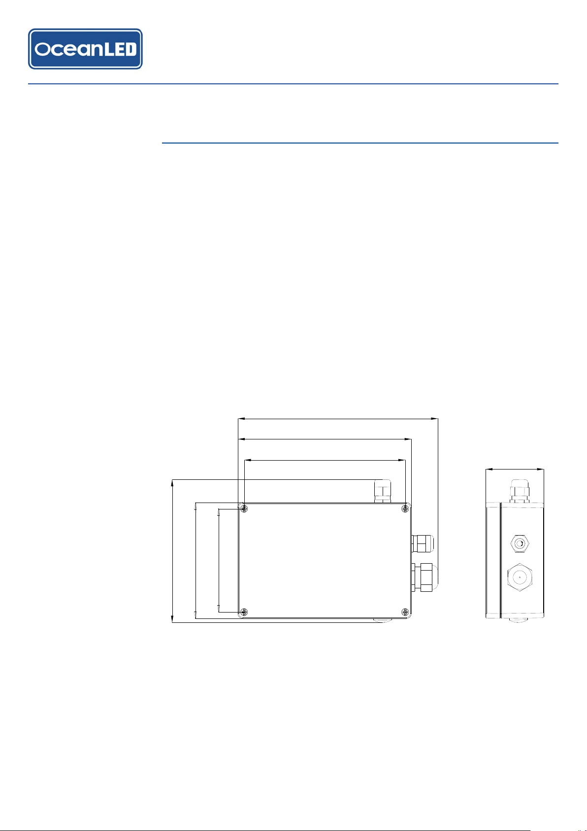
2.1 FINDING THE MOUNTING LOCATION
When choosing a mounting location for the OceanDMX Controller the following
recommendations need to be followed:
1. Consider the wiring routing / connections:
• The unit requires a 12 / 24 V DC power source
• The distance to the first DMX device / DMX Junction Box (i.e. check length of DMX
cable)
2.Select flat surface in a dry location away from sources of heat.
3.The unit should be mounted as high as possible in the vessel, and away from
metal objects to ensure good WiFi coverage. Avoid areas surrounded by metallic
insulation or coverings as this may interfere or restrict the WiFi signal.
4. To improve the responsiveness of the movement function the unit should be firmly
mounted to a solid surface directly connected to the vessels structure. (i.e not
mounted to a structure that will move or vibrate)
107mm
167mm
148mm
180mm
207mm
120mm
61mm
Mounted away from the rotational centre of the vessel – e.g. mount to one side of
the vessel, and either towards the bow or stern of the vessel. (This maximises the
accelerations the unit can detect due to wave motion).
Mounting
2
5
2019 INSTALL & OPERATION MANUAL
CONTROLLER KITS

Mounting
2.1 MOUNTING THE CONTROLLER
Once a suitable location has been found, use the following steps to mount the unit:
1. Unscrew the 4 case screws on the box, and remove the lid.
2. The mounting holes for the unit are located inside the box, near to each corner - see
diagram below.
3. The mounting screws that are provided should be suitable for most surfaces (such as
wood / fibreglass). Mark out the required mounting hole centres and drill pilot holes
as required – being careful to check for obstructions such as cables / pipes behind the
area being drilled.
4. Screw the unit to the surface using the screws provided.
Never use power tools. Hand tighten only!
2019 INSTALL & OPERATION MANUAL
CONTROLLER KITS
6

See the following example of Explore Series connections.
POWER IN
Control Link Cable
Control Cable
Example DC Installation (Explore Series)
POWER IN
TERMINATOR
KIT
Control Link Cable
POWER IN
Control Link Cable
POWER IN
12/24V DC FUSE
WiFi Communication
12/24V DC
12/24V DC
12/24V DC
12/24V DC
FUSE
FUSE
FUSE
FUSE
Installation (Explore Series)
3
7
2019 INSTALL & OPERATION MANUAL
CONTROLLER KITS

3.1 CONNECTIONS
OCEANDMX CONTROLLER TERMINAL CONNECTIONS
NAME FUNCTION CONNECTION
DC POWER
+DC POWER +VE CONNECT TO FUSED +12/+24 VDC FROM FUSE PANEL /
BATTERY
-DC POWER –VE / GND CONNECT TO BATTERY GND RETURN
EXT CTRL
GND
CURRENTLY UNUSED* DO NOT CONNECT*RX
TX
CONTROL OUTPUT
SHIELD CABLE SHIELD CONNECTION CONNECT TO CABLE SHIELD
DMX- DMX CONTROL SIGNAL –VE CONNECT TO DMX- (BROWN)
DMX+ DMX CONTROL SIGNAL +VE CONNECT TO DMX+ (YELLOW)
GND DMX GROUND CONNECT TO DMX GROUND (BLACK)
PWR SW EXTERNAL POWER ENABLE NOT USED FOR EXPLORE SERIES INSTALLATIONS
AUDIO AUDIO IN AUDIO LINE-IN 3.5MM STEREO JACK – CONNECT TO LINE OUT FROM
AUDIO SOURCE
EXT
SWITCHES
GND COMMON SWITCH GROUND SWITCH COMMON
SW 1 SWITCH 1
(SELECT PRE-SET FUNCTION) EXTERNAL SWITCH INPUT 1
SW 2 SWITCH 2 CURRENTLY NOT USED*
SW 3 SWITCH 3 CURRENTLY NOT USED*
*Reserved - to be implemented in future firmware releases
Installation (Explore Series)
2019 INSTALL & OPERATION MANUAL
CONTROLLER KITS
8

3.2 MAKING THE CONNECTIONS
All the connections (excluding the audio input) are made using push-type spring
terminals. Maximum cable size is 2.5mm2 (14 AWG).
To make a connection:
1. If required, strip back the wire – leaving approximately 4mm (5/32”) of the bare
conductor. Twist together ensuring that there are no stray strands.
2. Push & hold the plunger of the terminal down fully using a small terminal
screwdriver.
3. Insert the bare end of the cable into the terminal.
4. Release the terminal plunger
5. Test the terminal has clamped correctly by gently pulling on the wire
6. Check for stray strands that may cause shorts
3.3 POWER
12/24 V DC operation only – @12v DC max current draw = 300mA
A suitably fused 12 / 24 v DC supply is required to power the OceanDMX
controller.
DO NOT CONNECT TO MAINS AC! This can be sourced either directly from on-
board batteries or via a mains AC to 12V or 24V DC converter.
A minimum of 18 gauge (AWG) cable is recommended. THIS CABLE MUST BE
PROTECTED WITH A SUITABLE FUSE OR BREAKER (1 AMP RECOMMENDED).
0.3A MAX @ 12V DC
POWER INPUT
1. Select the required cable gland insert – two are provided, one suitable for a
multicore single jacket cable (already fitted inside the gland), the other for two
single wire conductors (provided in accessory kit).
2. Thread the cable / wires through the cable gland.
3. Connect the +VE terminal to a +12/24V fused power source.
4. Connect the –VE terminal to the battery – (Ground) supply.
5. Tighten the cable gland.
Installation (Explore Series)
!
9
2019 INSTALL & OPERATION MANUAL
CONTROLLER KITS

3.4 DMX
Loosen the cable gland, feed the cable end through and connect as follows:
(BLACK) DMX GROUND
(BROWN) DMX -
(YELLOW) DMX +
(NOT USED) POWER SW
SHIELD
3.5 AUDIO INPUT
3.5mm stereo input jack socket input:
AUDIO INPUT
For best results use the ‘line-out’ connection from an audio source, rather than a
headphone outlet, as levels should not change with volume.
Installation (Explore Series)
2019 INSTALL & OPERATION MANUAL
CONTROLLER KITS
10
Ce manuel convient aux modèles suivants
2
Table des matières
Autres manuels Oceanled Contrôleurs


