
Ocean Blue 400900 Guide de configuration

SAVE THESE INSTRUCTIONS
DEALER/INSTALLER: GIVE TO HOMEOWNER
Ocean Blue
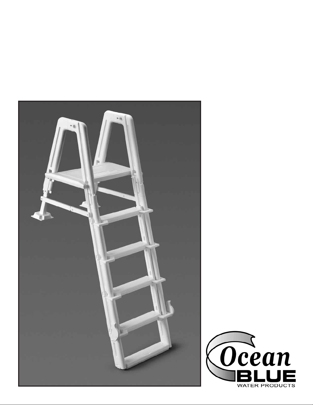
Outside Safety Ladder
Assembly and Installation Manual
Part no. 400900
Use with 30/38 entrance
systems or
400700 Grand Entrance
Above Ground Step to
make a complete system.
Outside safety ladder
alone can not be used to
enter/exit swimming pool.

- 1 -
Ocean Blue Outside Safety Ladder
Use with 30/38 Entrance Systems or
400700 Grand Entrance Above Ground Pool Step
ASSEMBLY INSTRUCTIONS - PLEASE READ BEFORE ATTEMPTING ASSEMBLY
Tools Needed for Assembly
■Rubber Mallet
■Cordless Drill w/Phillips
Driver
■5/16” Drill Bit
■Phillips Screwdriver
■Pliers
Parts List
■2 - Lower Outside Rails
■2 - Upper Outside Rails
■1 - Platform
■2 - Adjustable Braces
■1 - Locking Slide Tread
■3 - Slide Treads
■1 - Tread
■2 - Tread Connector
■2 - Locking Cams
■2 - Mounting Block Tubes
■2 - Mounting Blocks
■ 2 - Return Rails
■ 1 - Hardware/Safety Pack
Hardware Bag
■2 - Plugs
■20 - #10 x 1-1/4” Self-Tapping
Screws
■4 - #20 x 1/4” x 7/8” Bolts
■2 - 1/4” 20 x 3-1/2” bolts
■2 - 1/4” Flat Washers
■6 - 1/4” 20 Hex Nuts
■1 - Padlock
■1 - Instruction Manual
■1 - Safety/Warning Stickers
(2 per)
2 - Lower
Outside
Rails
2 - Upper
Outside
Rails
2 - Tread
Connectors
1 - Platform
2 - Locking
Cams
3 - Slide Treads
1 - Locking
Slide Tread
1 - Hardware/Safety Pack
2 - Adjustable
Braces
1 - Tread
2 - Mounting
Block Tubes
2 - Mounting
Blocks
2 - Return
Rails

- 2 -
Tools Needed: Cordless drill with Phillips bit
Step #1
#3: Place outside rail assembly
on a at surface. Place a return
rail over one of the outside rails
so that notches in the hooked
ends overlap and t together
smoothly.
#4: Attach rails using two
#10 x 1-1/4” self-tapping screws
(one in the designated mark on
the inside rail and one on the
outside rail). Repeat for remain-
ing return rail.
#5: Place rail assembly on edge
with return rails up. Position
platform so that tabs in platform
align with top holes in rails. Tap
in with rubber mallet. Position
remaining rail assembly so that
the tabs in platform align with
top holes in rails and tap in with
rubber mallet. Next tap both
sides platform down until rmly
seated in rails.
#6: With lad-
der assembly
still on edge.
Position bot-
tom tread so
tabs align with
the notches at
the bottom of
the rail assem-
blies and tap
in until tread
is properly
seated.
Parts needed to complete
step #1. #1: Place Lower Side Rail on
a at surface with notched end
facing up. Place Upper Side Rail
notched side down so it overlaps
the Lower Side Rail and both
pieces t together smoothly.
#2: Connect the Upper and
Lower Outside Rails together
using two #20 x 1/4” x 7/8” bolts
and two 1/4-20 hex nuts. Repeat
to assemble second Outside
Rail.

- 3 -
Step #2
Tools Needed: Rubber Mallet
#1: Place a
mounting block
small square
side down so
that the side
with the three
small holes is
closest to you.
Hold the
adjustable
brace with the
tab end up so
that the tab
end is angled toward you.
#2: Insert
adjustable
brace in the
center hole of
the mounting
block and tap
down with the
mallet.
#3: Turn mounting block assem-
bly over and tap the mounting
block down the adjustable brace
until it is seated snuggly at the
base of the brace. Repeat for
other mounting block assembly.
#4: With ladder assembly on
end, insert the mounting block
assembly into the hole in the
bottom of the return rail. Repeat
for other mounting block assem-
bly.
Tools Needed: Rubber Mallet, cordless drill with Phillips bit
#1: Arrange one locking slide
tread and three slide treads on
a at surface as shown in the
above picture. Place one tread
connector one each side of the
treads so that the rectangular
holes are angled up and out and
the end with the tab is positioned
at the bottom.
#2: Starting at
the bottom,
rotate one tread
connector on
edge. Align the
square tab on
the locking slide
tread with the
square hole in
tread connector.
Step #3
Locking Slide Tread
Three Slide Treads

- 4 -
Tools Needed: Rubber Mallet, cordless drill with Phillips bit
#3: Using a rubber mallet, tap
the tread connectors on to the
locking slide tread. Repeat for
remaining slide treads.
#4: Repeat step two to align the
rectangular holes in the remain-
ing tread connector with the tabs
on the slide treads. Turn slide
ladder assembly on edge and
tap tread connector down until
rmly seated.
#5: Align the hole in the locking
cam with the round tab on the
locking slide tread and tap down.
It may require several hits with
rubber mallet. Repeat on the
other side.
#6: Flip ladder assembly on to return rail side, lift and angle away.
Insert the slide ladder assembly into the grooves in the outside
rails assemblies and slide it all the way down to stops.
#7: Adhere safety/warning stick-
ers to platform and rail assem-
blies as shown.
Step #3 continued

- 5 -
Step #4
Attaching Outside Safety Ladder to Pool Step
CHOOSE A LOCATION THAT IS LEVEL AND IN FULL VIEW.
POOL MUST HAVE COMPETENT ADULT SUPERVISION AT ALL TIMES WHEN IN USE.
#1: Position the outside safety
ladder where it will attach to the
step in the swimming pool.
#2: Slide the mounting block as-
semblies down until the mount-
ing blocks sit on the top of pool
step. Next angle the ladder until
mounting blocks sit at. Mark
location on the mounting block
tubes.
#3: Pull outside ladder away
from pool, and attach both
mounting block assemblies to
the ladder using two #10 x 1-1/4”
self-tapping screws in each as-
sembly. Leave at least one hole
between screws.
#4: Position the ladder over
the pool step with the mount-
ing blocks sitting at on the top
tread. Center the ladder side-to-
side and front to back. Attach us-
ing four #10 x 1-1/4” self-tapping
screws in each mounting block.
#5: Cap holes located at the top
of rails using white plugs from
hardware bag. #6: Position one of the adjust-
able braces on the pool top
ledge next to the return rail and
outside rail. While holding in
place attach to each rail using
#10 x 1-1/4” self-tapping screw.
NOTE: Be careful not to block
channels of outside sliding lad-
der. Repeat for the other side.
Tools Needed: Tools Needed: cordless drill w/Phillips driver,5/16” drill bit, Phillips screwdriver, pliers.

#8: When the
pool is not in
use slide the
outside
portion of pool
ladder up until
the cams en-
gage into the platform recesses.
Install padlock through the lad-
der rail as shown.
- 6 -
Step #4 continued
#7: Using the braces as hole lo-
cators, drill two ¼” holes through
the pool top seat being careful
not to damage pool liner or wall.
Attach the ladder to the pool us-
ing two 1/4” – 20 x 3-1/2” bolts,
washers and hex nuts.
OUTSIDE TREADS MUST BE IN THE UP POSITION AND
LOCKED AT ALL TIMES WHEN POOL IS NOT IN USE.
Safety Rules
■Locate ladder on a solid base.
■ One person on the ladder at
a time.
■Ladder MUST be installed per
manufacturer’s instructions.
■DANGER: No Jumping or
Diving from ladder.
■Face ladder when entering
and leaving pool.
■To prevent entrapment or
drowning — DO NOT swim
through, behind or around
ladder.
■Ladder to be used as a
swimming pool ladder only.
■Weight limit -
300 lbs. maximum
■Warning: Exceeding the
maximum weight restriction
may cause the ladder to fail.
■When ladder is not in use,
slide up outside ladder
section and lock using
padlock. Ladder must be
locked at all times when not in
use or when there is no
qualied adult supervision.
■Consult your local Building
Department before installation
of your pool and equipment.
■DANGER: Use a cordless
drill for assembly and
installation. NEVER use an
electric drill in or around the
pool.

IMPORTANT For Your Safety
■Check the contents of the
carton with the parts list for
this ladder.
■DO NOT attempt to
assemble or install the ladder
if there are ANY shortages of
parts or hardware.
■For proper assembly and
installation follow all
instructions in the sequence
shown.
■Before using the product, after
assembly and installation, go
over the instructions and
procedures again to make
sure nothing has been
overlooked.
■Be sure and safe. The
manufacturer IS NOT
responsible for improper
assembly, installation and use.
MAINTENANCE:
To keep your new ladder work-
ing properly, just hose off once
a week with clean water. Check
the outside (slide up) ladder
for proper operation. Lubricate
tracks with silicon spray if neces-
sary. Check padlock for proper
operation, lubricate if necessary.
WINTERIZING:
Unfasten the ladder from pool
top seat and remove from the
water. Remove the plugs and lay
ladder on its side to drain. It will
take several minutes for the wa-
ter to drain out of the ladder rails
and treads. A small amount of
water left in ladder will not cause
any damage. Replace the plugs
so they won’t get lost.
OCEAN BLUE WATER PRODUCTS WARRANTY
Ocean Blue Water Products warrants their swimming pool ladders to be free from
defects in workmanship for one year from date of purchase.
DO NOT RETURN DEFECTIVE PART TO DEALER
The defective part should be returned, postpaid, to:
Ocean Blue Water Products
4646 W. Lake Street
Chicago, IL 60644
Enclose proof-of-purchase (receipts, etc.) showing date purchased, your name,
address, and daytime phone number.You will be notied of cost to replace part.
This warranty gives you specic legal rights, and you may also have other rights
which may vary from state to state.
Made in U.S.A • Printed in U.S.A.
CONSERVEZ CES DIRECTIVES
MARCHAND/INSTALLATEUR : REMETTEZ AU PROPRIÉTAIRE
Ocean Blue
Échelle de sécurité extérieure
Manuel de montage et d’installation
Pièce N° 400900
Pour utilisation avec les
systèmes d’entrée 30/38
ou la marche de piscine
hors terre Grand Entrance
400700 pour concevoir un
système complet.
L’échelle de sécurité exté-
rieure seule ne peut être
utilisée pour entrer dans
et sortir de la piscine.

- 1 -
Échelle de sécurité extérieure
Ocean Blue
Pour utilisation avec les systèmes d’entrée 30/38 ou
les marches de piscine hors terre Grand Entrance 400700.
DIRECTIVES DE MONTAGE – LISEZ AVANT DE TENTER LE MONTAGE
Outils nécessaires pour le
montage
■Maillet en caoutchouc
■Perceuse sans l avec
mèche pour vis étoilée
■Mèche 5/16po
■Tournevis à pointe étoilée
■Pinces
Liste des pièces
■2 - Montants inférieurs
■2 - Montants supérieurs
■1 - Plate-forme
■2 - Étrésillons réglables
■1 - Marche de glissière à
verrou
■3 - Marches de glissière
■1 - Marche
■2 - Raccords de marche
■2 - Cames de verrouillage
■2 - Tiges de patte de retour
■2 - Pattes de retour
■ 2 - Montants de retour
■ 1 - Trousse de quincaillerie/
sécurité
Trousse de quincaillerie
■2 - Bouchons
■20 vis autotaraudeuses
#10x11/4po
■4 - Boulons
#20x1/4pox7/8po
■2 - Boulons 1/4po
20x31/2po
■2 - Rondelles plates 1/4po
■6 - Écrous hexagonaux
1/4po 20
■1 - Cadenas
■1 - Manuel de directives
■1 - Autocollants
d’avertissement/sécurité
(2autocollants)
2 - Montants
inférieurs
2 - Montants
supérieurs 2 - Raccords
de marche
1 - Plate-forme
2 - Cames de
verrouillage
3 - Marches de
glissière
1 - Marche
de glissière à
verrou
1 - Trousse de quincaillerie/sécurité
2 - Étrésillons
réglables
1 - Marche
2 - Tiges de
patte de retour
2 - Pattes de
retour
2 - Montants
de retour
Table des matières
Langues :
Autres manuels Ocean Blue Échelle


