Numato 2 Channel USB Relay Module Manuel utilisateur
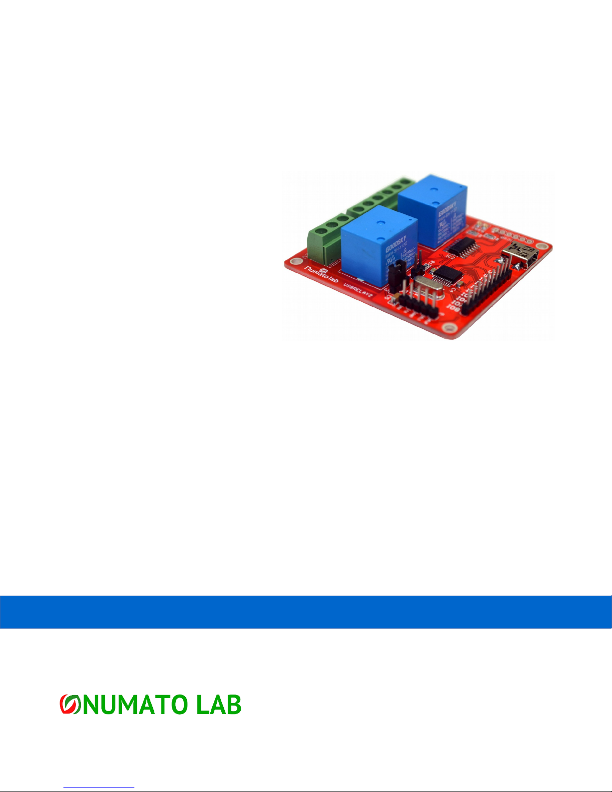
2 Channel USB Relay Module
User Guide
www.numato.com

Get in touch with us!
Please feel free to send a mail to one of the mail IDs below or use the form a ailable at the Contact Us
page at http://www.numato.com
Technical Help
Got technical questions? Please write to [email protected]om
Sales Team
Questions about making payments, olume discounts, academic discounts, purchase orders and
quotes? Please write to sales@numato.com
Webmaster
Questions/Suggestions about our website? Please write to webmaster@numato.com
Like us at Facebook! https://www.facebook.com/numato
Visit our blog http://www.numato.cc
Mailing Address
NO 29,NEW MICO LAYOUT
16TH MAIN, BEGUR ROAD
HONGASANDHRA
BANGLORE, KA -560068
INDIA
* Mail orders, phone orders and direct pick up are not a ailable at this time. Please isit our online store to place your order. Estimated shipping time to
your address will be displayed in the shopping cart before checkout.
All trademarks are property of their respecti e owners.
You may use, modify or share this publication or part of thereof adhering to Creati e
Commons Attribution-ShareAlike 3.0 Unported (CC BY-SA 3.0) License.
See complete license text at http://creati ecommons.org/licenses/by-sa/3.0/

1 2 Channel USB Relay Module – User Guide
Introduction
Numato Lab's 2 Channel USB Relay Module is a ersatile product for controlling your electrical and
electronic de ices remotely from a PC o er USB link. Ease of use and wider operating system
compatibility were the primary goals behind this product's design. Built in USB to serial con ersion
allows the module to be used e en with no USB specific knowledge. This simplicity allows use of off-
the-shelf Terminal Emulation programs such as Hyper Terminal and PUTTY for controlling the module
with a simple set of human readable commands. For power users, this module can be controlled by
writing programs in arious languages.
Some of the possible uses of this module include
•Home Automation
•Lighting Control
•Garden Equipment Control
•Industrial Automation
•Test Fixtures
•DIY and Hobby
This product is compatible with the following operating systems.
•Windows XP and later
•Linux
•Mac
•And any other operating system that supports USB CDC de ices.
And these are some of the languages that can be used for programming.
•C/C++
•Visual Basic (VB6, VB2008, VB2010 regular editions and express editions)
•Visual Basic for Applications (Microsoft Office VBA)
•Perl
•Python
•JAVA
•And many more...
This module has two on board relays and associated dri ers capable of controlling a large number of
de ices including lamps, motors, locks etc... (Please see recommendations for using this product with
inducti e loads elsewhere in this document). This module also includes General Purpose I/Os, and
analog inputs (multiplexed with GPIOs) that can be accessed o er USB interface for extended
functionality. The module communicates with host PC o er full speed USB link. When connected to
PC, the module will appear as a serial port in Windows De ice Manager (or a serial tty de ice in Linux
and Mac).

2 2 Channel USB Relay Module – User Guide
How to use the module
The following section describes how to use this module.
Components/Tools required
Along with the module, you may need the items in the list below for easy and fast installation.
1. USB A to B or A to Mini B cable depending on the product model you ha e purchased
2. +12V 1A power supply
3. Medium size Philips screw dri er
Connection Details
The following connections needs to be made before using this module.
IMPO TANT Please exercise utmost caution while working with electrical mains or other
high voltages. Failure to comply with safety regulations may result in injury and or death.
Connection Diagram
Abo e image shows basic connection diagram that can be used in most of the situations. The
connection diagram is same for both AC and DC loads. Please make sure to use a freewheeling diode
or snubber circuit if the load is inducti e. More details about using inducti e loads is a ailable
elsewhere in this document. Use a USB A to B or A to Mini B cable for connection to PC depending on
the model you ha e purchased. It is important to make sure that the wires used to connect loads are
rated sufficiently. Exercise caution while working with high oltages. Short circuits can cause damage
to the module and the PC. The following sections identify indi idual connections in detail.
!

3 2 Channel USB Relay Module – User Guide
USB Interface
This module has an on board full speed USB controller that helps a PC/Linux/Mac computer to
communicate and control seamlessly. Depending on the module you ha e
purchased, you will need to use a USB A to B or USB A to Mini B cable. Please
isit the product page at http://www.numato.com to see a ailable USB
connector options. By default, the logic section of the module is powered
from USB so make sure not to o ercrowd unpowered USB hubs. (the picture
on the right shows USB Mini connector)
Visit http://numato.com/cables-accessories to buy cables and accessories for this product.
Relay Contacts
All contacts on each relay on this module is a ailable externally on screw terminals for easy user
access. The relay are rated for AC and DC supply oltages. Please see the electrical parameter table for
more details. Each relay has three contacts, namely C, NO and NC. C is the
common terminal and is used in both normally open and normally closed
positions. The contacts NC and C will be connected when the relay is turned
off and will be disconnected when relay is turned on. And ice ersa, the
contacts C and NO will be disconnected when relay is turned off and will be
connected when the relay is turned on. The table below summarize the relay
contact positions.
Relay State Connection between NC and C Connection between NO and C
OFF Close Open
ON Open Close
DC Power Supply
This module requires two power supplies to function properly. A +5V supply for the logic circuit and a
+12V supply for the relay coils. By default the board is configured to use +5V supply from USB. So an
external +5V power is not required unless USB port is unable to supply
enough current. In most cases USB ports are capable of providing
enough current for the module. The +12V supply for the relay coils is not
optional and the relay will not switch without this supply. Any off the
shelf 12V DC power supply can be used for this purpose. Make sure to
connect the power supply in correct polarity. Connect the positive
terminal of the power supply to the +12 terminal on the module. Connect
negative terminal of the power supply to GND terminal of the module.
Connecting power supply incorrectly can cause damage to the module and/or other de ices.
If for any reason, an external 5V power supply needs to be used for the logic section of the module,
the Jumper JP1 should be configured properly before connecting the power supply. When using

4 2 Channel USB Relay Module – User Guide
external 5V power supply, the jumper should be mo ed to 1-2 position. Please refer to the marking on
the board for more details. Make sure to connect the power supply in correct polarity. Connect the
positive terminal of the power supply to the +5V terminal on the module. Connect negative terminal
of the power supply to GND terminal of the module. Connecting power supply incorrectly can cause
damage to the module and/or other de ices. Remember, an external 5V supply is optional in most
cases.
GPIO/Analog inputs (optional)
In addition to onboard relays, this product has eight General Purpose IO pins that can be used for
arious custom applications. Some of these pins can be used as Analog to Digital Con erter inputs as
well. All IO pins support 5V TTL signals and the ADC input range is 0 to +5V.
The ADC can acquire analog signal at the resolution of 10 bits per sample.
It is recommended to use a series resistor with the GPIO/ADC pins when
interfacing with other circuits. In output mode, each GPIO can source up to
20mA. So no additional circuitry is needed to dri e regular LEDs. A 470
Ohms series resistor is recommended for current limiting when connecting
LED to a GPIO.
In contrast to GPIOs Analog inputs can read oltages at any le el between
0 to 5 olts. It is recommended to use a series resistor to protect the input from stray oltages and
spikes. The internal Analog To Digital con erter supports 10 bits resolution which is adequate for most
applications.
The table below summarizes the GPIO and Analog to Digital Con erter input positions on the header.
Pin number on the header GPIO ADC
1 VDD VDD
2 GND GND
3 IO1 ADC0
4 IO2 ADC1
5 IO3 ADC2
6 IO4 NA
7 IO5 NA
8 IO6 ADC3
9 IO7 ADC4
10 IO8 ADC5

5 2 Channel USB Relay Module – User Guide
TTL Relay Dri er Inputs (optional)
Optionally the relays can be controlled by using the two a ailable TTL inputs
(RL0, RL1) in case USB functionality is not needed. This can be ery handy if
the relays need to be switched on/off using a microcontroller or parallel
port. A 5V signal at these inputs will turn the corresponding relay on and
0V/Ground or lea ing the input open will turn the relay off.
Serial IO (optional)
This board supports a serial interface which can be used to control relays
using a microcontroller or a PC serial port o er a standard RS232 data
interface. The Serial Interface pins do support only 5V logic. So to connect
to a standard PC Serial Port, a le el translator such as MAX232 is required.
This interface supports a single byte command which can be used to read or
write relay status. A response byte will be sent by the board only for read
requests. To confirm if a write command was successful, the status of the
relay should be queried. Please see the table below for command details.
Command
Bit Position Definition
7 0 – Write
1 – Read
6
Value to be written during a write command.
0 – Turn off relay
1 – Turn on relay
5 Reser ed
4 – 0 Relay index
Response
Bit Position Definition
7 Reser ed
6 Relay Status
0 – Relay Off
1 – Relay On
5 Reser ed
4 – 0 Relay Index

6 2 Channel USB Relay Module – User Guide
Driver Installation
Windows
This product requires a dri er to be installed for proper functioning when used with Windows. The
dri er package can be downloaded from the product page.
To install the dri er, unzip the contents of the downloaded
dri er package to a folder. Attach USB cable to the PC and
when asked by Windows de ice installation wizard, point to
the folder where dri er files are present. When dri er
installation is complete, the module should appear in
Windows De ice Manager as a serial port (see the picture on
the right). Note down the name of the serial port (COM1,
COM2 etc..). This information is required to control the module from the PC.
Linux
To use this product with Linux, USB CDC dri er needs to be compiled in with the kernel. Fortunately,
most Linux distributions (Ubuntu, edhat, Debian etc..) comes with this driver pre-installed. The
chances of you requiring to rebuild the kernel to include the USB CDC dri er is ery slim. When
connected to a Linux machine, this product should appear as a serial port in the /de directory.
Usually the name of the de ice will be “ttyACMx” or similar. The name may be different depending on
the Linux distribution you ha e.
Mac
Similar to Linux, Mac operating system comes with the required dri ers pre-installed. When connected
to a Mac computer, the de ice should appear as a serial port.
Sending Commands
One of the most powerful features of this module is the simple easy to use command set it supports.
This command set hides the complex USB protocol and gi es a ery simple interface to access the
features of the module. The following sections gi e details of the command set and how to use the
command set
The command set
This product supports a ery simple command set that is designed to be less cryptic and easy to use
manually (using serial terminal emulation programs) or through a program written in many supported
languages.

7 2 Channel USB Relay Module – User Guide
List of currently supported commands
No. Command Parameters Example Description
1 er None er Returns firmware Version
2 relay on/off/read, relay
number
relay on 0 Relay control
3 reset None reset Reset relays to default state
(all relays turned off)
4 adc read, channel adc read, 0 Read Analog to Digital
Con erter input
5 gpio set/clear/read,
gpio number
gpio set 0 Control General Purpose
Input/Output
The table below has more detailed information about a ailable commands.
No. Command Example Description
1 er er Returns current firmware ersion.
2 relay
relay on x
Turns a particular relay on. In this command, the parameter “x
“ stands for the relay number. The relay number starts from
zero. See some examples below.
relay on 0 – Turns on relay 0
relay on 1 – Turns on relay 1
relay off x
Turns a particular relay off. In this command, the parameter “x
“ stands for the relay number. The relay number starts from
zero. See some examples below.
relay off 0 – Turns off relay 0
relay off 1 – Turns off relay 1
relay read x
Returns the status of a particular relay. In this command, the
parameter “x “ stands for the relay number. The relay number
starts from zero. See some examples below.
relay read 0 – Returns status of relay 0
relay read 1 – Returns status of relay 1
The data returned in response to this command will be either
“on” or “off” depending on the current status of the relay.
3 reset reset Resets all relays to off state which is the default state. GPIOs
are not by affected by the command.

8 2 Channel USB Relay Module – User Guide
4 adc adc read x
Reads the analog oltage present at the ADC input mentioned.
X stands for the number of ADC input. The response will be a
number that ranges from 0 – 1023. Please see examples below.
adc read 0 – Reads analog input 0
adc read 4 – Reads analog input 4
5
gpio
gpio set x
Sets the GPIO output status to high. Here x is the number of
the GPIO. Please see examples below.
gpio set 0 – Sets GPIO 0 to high state
gpio set 4 – Sets GPIO 4 to high state
gpio clear x
Sets the GPIO output status to low. Here x is the number of the
GPIO. Please see examples below.
gpio clear 0 – Sets GPIO 0 to low state
gpio clear 4 – Sets GPIO 4 to low state
gpio read x
Reads the digital status present at the input mentioned. Here x
stands for the number of GPIO. The response will be either
“on” or “off” depending on the current digital state of the
GPIO. Please see examples below.
gpio read 0 – Reads GPIO 0 status
gpio read 4 – Reads GPIO 4 status
Controlling relays using Serial Terminal Emulator software
The simple set of ASCII based human readable command set supported by this module makes
controlling relays easy with any off the shelf Serial Terminal Emulation program like Hyper Terminal or
Teraterm. The most important thing to remember here is that since the module appear as a serial
port in the operating system, treat it just like any serial de ice you may use. Since the underlying
transport is USB not RS232, almost all settings such as baud rate, parity, number of stop bits can be
left to the default alues in the software. Flow control needs to be set to “None”. The following
sections gi e examples of how to use the module with Hyper Terminal and Teraterm.
Using this module with Hyper Terminal is ery easy. Please follow the steps below.
•Connect the module to the computer, install dri er and note down the name of the new serial
port that appears in the de ice manager.
•Open Hyper Terminal and select the serial port corresponding to the relay module. Click OK.
Table des matières


