NOHMI FDGJ103-D-X/XHT Manuel utilisateur

5mー100m
OPERATING MANUAL
Projected Beam Type Smoke Detector
Models FDGJ103/203-D-X/XHT
TN51541e-1
CAUTION Be sure to read this manual before use of this product. In addition,
carefully read and understand all the warning/cautions/notes in this
manual to use/operate this product.
● Please keep this operating manual in place so that it may be available at all
the times.
● Be sure to conduct the regular inspection and maintenance for this product.

INTRODUCTION
CONTENTS
Thank you for purchasing our projected beam type smoke detector. This detector
has passed various tests in accordance with the standards of the Japanese Fire
Service Law and is approved as the national type approval product.
Be sure to read this manual carefully before use of this product to properly
use/operate this product in case of fire. Please keep this operating manual in
place so that it may be available at all the times.
1. FEATURES OF THIS PRODUCT• • • • • • • • • • • • • • • • • • • • • • • • • •
2. BEFORE USE• • • • • • • • • • • • • • • • • • • • • • • • • • • • • • • • • • • • • • •
3. CAUTIONS FOR USE • • • • • • • • • • • • • • • • • • • • • • • • • • • • • • • • •
4. CAUTIONS ON INSTALLATION WORK AND OPERAION • • • • • • • •
5. ITEMS REQUIRED FOR INSTALLATION• • • • • • • • • • • • • • • • • • • •
6. NAME OF EACH PART • • • • • • • • • • • • • • • • • • • • • • • • • • • • • • • •
7. WORK FLOW• • • • • • • • • • • • • • • • • • • • • • • • • • • • • • • • • • • • • • •
8. CONNECTION WITH FIRE CONTROL PANEL• • • • • • • • • • • • • • • •
9. INSTALLATION/CONNECTION/SETTING • • • • • • • • • • • • • • • • • • •
10. CONNECTION OF HEATER (HEATER TYPE ONLY)• • • • • • • • • • •
11. LIGHT AXIS ADJUSTING METHOD• • • • • • • • • • • • • • • • • • • • • • •
12. LIGHT AXIS ADJUSTING METHOD (FLICKERING PATTERN)• • • •
13. TROUBLESHOOTING• • • • • • • • • • • • • • • • • • • • • • • • • • • • • • • •
14. REGULAR MAINTENANCE & INSPECTION • • • • • • • • • • • • • • • •
15. SPECIFICATIONS• • • • • • • • • • • • • • • • • • • • • • • • • • • • • • • • • • •
1
1
2
3
4
5
7
8
9
11
12
17
19
22
23

- 1 -
1. FEATURES OF THIS PRODUCT
2. BEFORE USE
WARNING
CAUTION
● Sensitivity Compensation Function to Keep Stable Function
: The detector sensitivity is automatically compensated and adjusted even in
case that the level of the light received by the light receiver is decreased due
to contamination on the detector lens surface.
● Light Axis Adjustment without Voltmeter (Tester)
: Light output can be checked by means of the light emitting pattern of the
indicator lamps, without using a voltmeter.
● Easy Installation
: This product can be installed as an unit with the assembled state by
changing the assembling Combination of the base, the cover and the body
depending on the installation site conditions.
● To use this product safely, this operating manual contains various cautions.
Before using this product, understand the following caution markings together
with the statements and read this manual. When using this product, be sure to
bring this manual at all times.
Mishandling may result in the user exposed to serious injuries or damage.
Failure to observe these guidelines may also cause serious damages to a part
of the fire protection function of the product.
Mishandling may result in the user injuries. Failure to observe these guidelines
may also have an adverse effect on the fire protection function of the product.
It is important to observe these guidelines at all times in order to effectively
utilize the fire protection functions over long-term use.
This mark shows a matter related to Danger, Warning or Caution.
■ CAUTION Markings
This mark shows an action to be taken or the instructions on
actions.
This mark shows the prohibition of actions.
- 2 -
3. CAUTIONS FOR USE
● Where it is directly exposed to rain or water.
● Where smoke or mist is usually generated.
● Where the light receiver is subjected to direct sunlight or strong
illumination light.
● Where the ambient temperature is lowered below -10°C or
exceeds 50°C.
● Where the mounting position of the detector is subjected to
vibration or strain. (Install the detector on a rigid position such as a
support/pillar of the main structure.)
● Where it is difficult to perform maintenance and inspection.(Space
of 50cm in vertical and horizontal directions (50cm each in
left/right/up/down directions) is required for surrounding of the
detector. In case that the ceiling height is 2.5 m or lower, pay
attention to the upper space. Example: If the ceiling height is
2.1m, the upper space is to be 42cm.)
● Where the light axis (between the light transmitter and receiver)
may be interrupted due to transportation of objects or a
transparent obstacle such as glass.
● In a place where a ball or a bar is usually used, such as
gymnasium, apply the protective cover (Model FZP014).
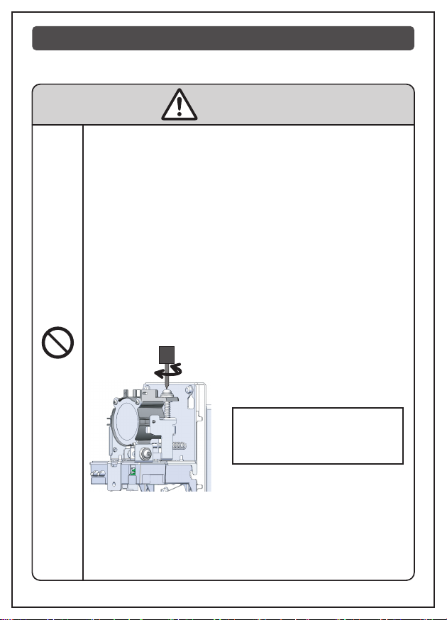
As this product is not of outdoor type, DO NOT install it in any of the following
places. (If installed, it may cause a malfunction or abnormal operation.)
Space for a screwdriver is required in the
above of the detector.
Prohi-
bition
Installation Standard :
The detector shall be installed so
that the height of the light axis
exceeds 80% of the ceiling
WARNING

- 3 -
4. CAUTIONS ON INSTALLATION WORK
AND OPERATION
● Be sure to arrange a secure scaffold.
● Make sure that nobody is located under the worker installing the
detector.
● Turn OFF the power supply of the fire control panel and remove
the battery provided in the panel as the auxiliary power. (Excl. the
case for light axis adjustment after installation work)
● Ensure that this product is not damaged due to drop, impact or
handling of a tool.
● DO NOT touch the front plate nor the lens. (If touched, the front
plate or the lens may contaminated, causing an adverse effect on
the detector function.)
● The Models FDGJ103/203-D-XHT are equipped with a heater.
As the heater becomes hot, NEVER touch. If touched, you may
get burnt.
(Position of heater Refer to 6. NAME OF EACH PART on
Page 6.)
● NEVER apply any vibration or impact/shock to the product,
disassemble/modify the product, or insert any foreign material into
the product, as these actions may cause a fault in the product.
● As this product is a component device of the automatic fire alarm
system stipulated in the Japanese Fire Service Law, do not use it
for any other applications.
When installing and operating this product, pay attention to the following matters.
Prohi-
bition
WARNING
INSTRUC-
TIONS

- 4 -
5. ITEMS REQUIRED FOR INSTALLATION
To install this product, the following items are used.
Arrange them according to the necessity.
No.
1
DESCRIPTION
Phillips type screwdriver For M4 and M5 screws
Test filter set (Model FXG012C)
REMARK
2
Battery connector for detector
test
If the auxiliary battery (for test) (24V,
with connector) is used, arrange it.
3
4
Solderless tool and terminals
(with heater type)
Auxiliary battery (for test)
(24V, with connector)
The light axis of this detector can be
adjusted with the auxiliary power
supply (Battery, 0.225AH to 3.5AH ).
In case of the detector with heater,
connection of the heater power is
made with solderless method.
(AWG22(0.3mm2) and AWG20
(0.5mm2) wires one each)
5

- 5 -
Light transmitter
Left :Power lamp
(Green)
Right:Test lamp
(Red)
6. NAME OF EACH PART
Cover Body fixing screwFront plate
Cover fixing screw
Light axis adjusting
screw (Vertical)
Collimation
hole
Light receiver
Left :Fire alarm lamp
(Red)
Right:Trouble lamp
(Yellow) Lens
Body
Indicator lamp
Cover hook
Viewing hole
Light axis adjusting
screw (Horizontal)
MONITOR/ADJUST.
Switch
Body fixing screw

- 6 -
Heater (Heater type only)
Battery connector
Tarminal base
Name plate Name plate
Light receiver
Light transmitter
Bottom view
Right side viewLeft side view
Range setting switch
(Light receiver only)
Sensor output jack
(Light transmitter only)
Light axis adjusting
screw (Horizontal)
Light axis adjusting
screw (Vertical)

- 7 -
7. WORK FLOW
Install this product according to the following work flow.
We recommend to install the light receiver first.
Light Receiver
①Installation • • • • • • • • • • • • • • • • • • • • • • • • • • • •
②Connection • • • • • • • • • • • • • • • • • • • • • • • • • • • •
③Setting • • • • • • • • • • • • • • • • • • • • • • • • • • • • • • •
④Adjustment (Coarse adjustment) • • • • • • • • • • • • •
※Fine adjustment is not required for the light receiver.
Light Transmitter
⑤Installation • • • • • • • • • • • • • • • • • • • • • • • • • • • •
⑥Connection • • • • • • • • • • • • • • • • • • • • • • • • • • • •
※Setting is not required for the light transmitter.
⑦Adjustment (Coarse adjustment) • • • • • • • • • • • • •
⑧Adjustment (Fine adjustment) • • • • • • • • • • • • • • •
Page9 to Page10
Page8 and Page10
Page11 (Heater type only)
Page10 to Page11
Page12
Page9 to Page10
Page8 and Page10
Page11 (Heater type only)
Page12
Page13 to Page18

- 8 -
Connection shall be made as shown below.(Applicable wire for the terminal
base of the detector is a single line, φ0.4 to φ1.6.)
● Line resistance between the fire control panel and the light receiver of the
detector (C-L, KT1-KT2) shall be 50Ω or less.
● Line resistance between the light transmitter and the light receiver of the
detector (LE1, LE2) shall be 30Ω or less.
※As the remote indicator lamp FLL061 and the signal transmission adaptors
FRL014,pay attention to the polarities of the terminals XL1 and XL2.
As the synchronization lines(LE1(+), LE2(-))has the polarities, pay attention to
their connection. As for connection of the heater, refer to
10. CONNECTION OF HEATER (HEATER TYPE ONLY) on Page11.
8. CONNECTION WITH FIRE CONTROL
PANEL
Power supply for heater
Test push button
Light receiver Light transmitter
Next detector
P- type
(conventional)
fire
control
panel
Ce manuel convient aux modèles suivants
1
Table des matières
Autres manuels NOHMI Capteur de sécurité


