NKE GYROPILOT 2 Manuel utilisateur

Zi de Kerandré – Rue Gutemberg – 56700 – HENNEBONT – FRANCE
www.nke-marine-electronics.com
+33 297 365 685
GYROPILOT 2 computer
product reference : 90-60-130
INSTALLATION GUIDE
REV 2

- 2 - Gyropilot_2_um_EN_7_30
SOMMAIRE
1 PRESENTATION ............................................................................................................ 3
2 INSTALLING THE HYDRAULIC UNIT ........................................................................... 5
2.1 PREPARING THE RUDDER ARM......................................................................................... 5
2.2 INSTALLATION OF THE HYDRAULIC LINEAR DRIVE ................................................................ 6
2.3 INSTALLATION OF THE HYDRAULIC PUMP ........................................................................... 8
2.4 INSTALLATION OF THE RUDDER ANGLE SENSOR ................................................................. 8
3 INSTALLATION AND CONNECTING THE COMPUTER ............................................. 10
3.1 PACKING LIST ............................................................................................................... 10
3.2 LIST OF ACCESSORIES .................................................................................................. 10
3.3 INSTALLING AND LOCATION OF THE COMPUTER GYROPILOT 2 ............................................ 10
3.4 ELECTRIC DIAGRAM OF GYROPILOT 2 RVP COMPUTER (REVERSIBLE PUMP) ...................... 11
3.5 ELECTRIC DIAGRAM GYROPILOT 2 CRP COMPUTER ........................................................ 13
3.6 CONNECTING THE POWER SUPPLY OF THE LINEAR DRIVE MOTOR ....................................... 15
3.7 CONNECTING THE COMPUTER TO TOPLINE BUS ............................................................... 16
3.8 TECHNICAL SPECIFICATION ............................................................................................ 17
3.9 SOFTWARE COMPUTER VERSION .................................................................................... 17
3.10 DIAGNOSTIC FOR 1ST LEVEL TROUBLES SHOOTING. ....................................................... 17
4 INITIALISATION OF THE COMPUTER ........................................................................ 18
4.1 INITIALISATION .............................................................................................................. 18
4.2 FIRST START-UP OF THE PILOT ....................................................................................... 19
- 3 - Gyropilot_2_um_EN_7_30
1 PRESENTATION
This installation guide gives you all information :
- To install the computer Gyropilot 2
- To install rudder angle sensor
- To install de the hydraulic unit
- To get the optimal performances from your pilot and your boat.
See the installation guide for fluxgate compass and multifonction Gyrographic.
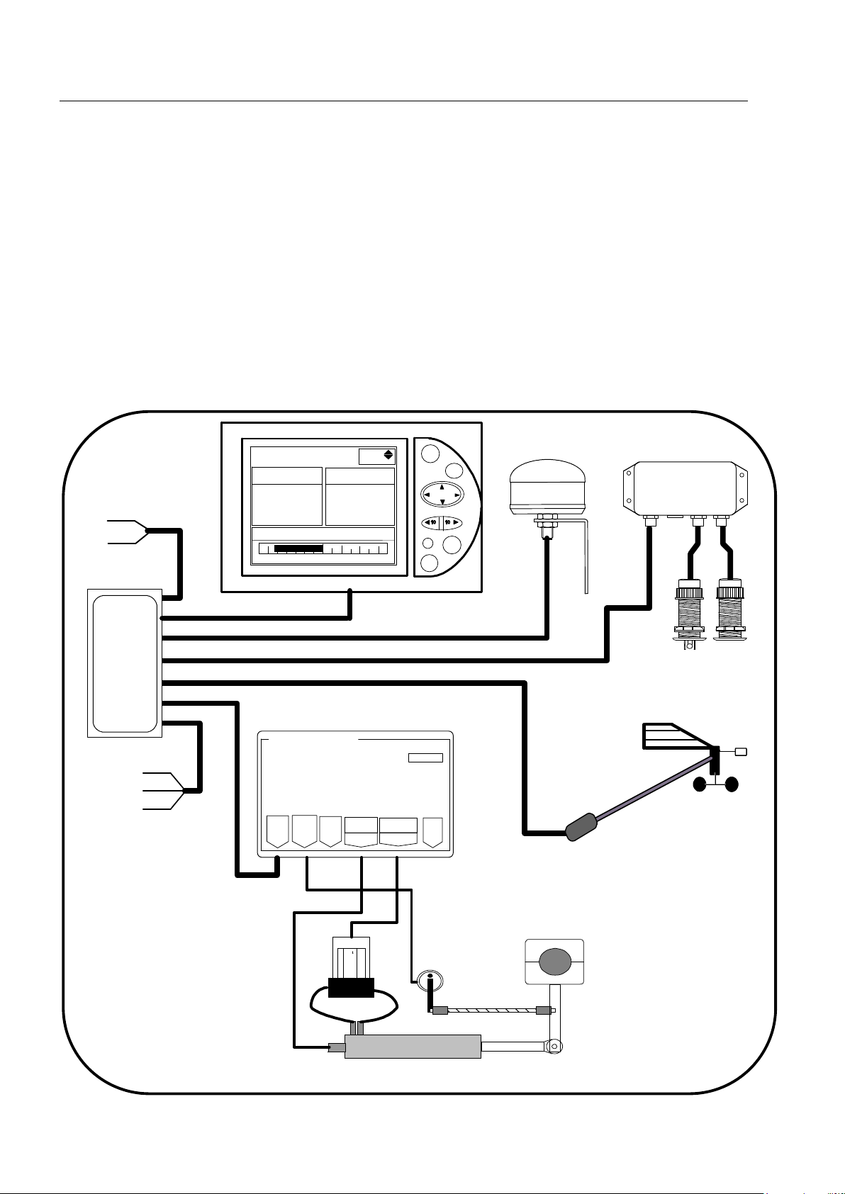
Installation architecture
The presence of the equipment in the following diagram is for information only, and does
not represent the equipment of your installation.
nke Gyrop
i
lot 2
CRP
RVP
RVP
Calculateur Gyro2
Bus
Angle
Barre Tiller
Embrayage Alim.
Pompe
réversible
TOPLINE câble
20-61-001
GND
DATA black
12VDC white
Figure 1
loch depth interface
90-60-450
loch
speedomètre
depth
Connecting box
90-60-417
NMEA -
NMEA +
Input NMEA
11
Auto
Stop
Page
Ent
True wind mode G5
Reference True wind
Rudder angle
0
-10 10
-30° -30°
Gyropilote Graphic
nke
M
nke
Helm spindle
Rudder angle
hydaulic ram
Masthead unit

- 4 - Gyropilot_2_um_EN_7_30

- 5 - Gyropilot_2_um_EN_7_30
35° 35°
Rudder Arm
Rudder Shaft
2 INSTALLING THE HYDRAULIC UNIT
Read this guide entirely before starting the installation .
Read the installation manual the hydraulic linear drive manufacture.
2.1 Preparing the rudder arm
If it is not possible to install the drive unit directly to the steering quadrant, then you will
have to buy and install a rudder arm for your rudder shaft. The rudder arm can be mounted
on the rudder shaft in any direction.
Make sure that the ruder arm can freely move 35° in both directions and that there is
enough room available to mount the drive unit and rudder angle sensor as per the following
sections.
Check with your boat manufacturer for special instructions on mounting autopilots to your
rudder shaft or your quadrant
Drill a 16mm hole to mount the hydraulic linear drive axis:
- 240mm from ruder axis for pack type 60
Drill a 14mm hole to mount the hydraulic linear drive axis:
- 190mm from ruder axis pack type 40
- 170mm from ruder axis pack type 32
- 150mm from ruder axis pack type 27
Drill a 12mm hole to mount the hydraulic linear drive axis:
- 129mm from ruder axis pack type mini

- 6 - Gyropilot_2_um_EN_7_30
2.2 Installation of the hydraulic linear drive
2.2.1 Linear drive for inboard mounting
You will find with the hydraulic linear drive, the manufacturer mounting instructions.
Dimensions for installation
Pack type B
the rod half the way out F G
60 727mm 240mm 218mm
40 627mm 190mm 172,5mm
32 533mm 170mm 160mm
27 472mm 150mm 136,5mm
Mini 395mm 129mm 117mm
WARNING:
The force developed by a hydrauli
c linear drive is very strong and could result in serious
damage if impropally installed.
The linear drive and the hydraulic pump must be positioned on an horizontal plan.
Make sure that the linear drive support is positioned in the way that the
rudder arm or rudder
sector is in the same horizontal plan as the linear drive axis.
The mounting
of the linear must be very rigid and you should not hesitate to strengthen it with
a stainless steel plate strongly attached to the boat.
The rod of the cylinder is very fragile, and must not receive shocks, which could cause the rip
of the lip seal and therefore an oil leak.
Rudder arm
Rod tip

- 7 - Gyropilot_2_um_EN_7_30
2.2.2 Hydraulic linear drive type 40 for outboard mounting
You will find with the hydraulic linear drive, the manufacturer mounting instructions.
Dimensions for installation hydraulic linear drive type 40 outboard
2.2.3 Installation procedure
- Put the rudder to the axis
- Unscrew half the way the tip at the end of the drive rod, and pull the rod half the way out
such as the length between the axis of the linear support and the thrust axis is equal to
the rod length
- Place the linear drive at 90° of the rudder arm
- Fixed it with 4 stainless steel screws and nuts.
- Grease the thrust axis of the linear drive and fix it on the rudder arm or rudder sector
with the supplied nylstop nut.
- Adjust the rod tip on the same axis than the thrust axis and block it in position with the
counter-nut.
- Insert the thrust axis in the rod tip and block it with a lynch pin.
WARNING:
Check that the mechanical rudder stops are in use. If the l
inear drive is used as a rudder
stop, it could be irremediably damaged.

- 8 - Gyropilot_2_um_EN_7_30
2.3 Installation of the hydraulic pump
Select a location where it is easy to access to the pump for maintaining : oil adjust, speed
setting.
Fix the pump with 4 screw and nuts 6mm, on an horizontal plan.
WARNING:
Don’t forget before start up , remove the shipping cap on the top of the oil tank
and replace it
by the evented cap supplied with the hydraulic unit.
2.4 Installation of the rudder angle sensor
2.4.1 Precautions
- The sensor arm must be able to move ± 90° UNOBSTRUCTED.
- When the rudder is centred, the sensor arm must also be centred (in relation to the axis
screw head-see below).
- Distance “A” must be equal to “B”.
- The sensor connector must be 90° to the rudder arm when the rudder is centred.
- It must be installed in a safe/dry location and away from interfering equipment (radio
receivers, compressors, speakers, generators, etc.)
- The mounting location must be rigid and with the sensor arm and the rudder arm in
the same horizontal plan.
Correct mounting Not allowed

- 9 - Gyropilot_2_um_EN_7_30
2.4.2 Installation procedure
1. Present the threaded rod in front of the rudder shaft, measure the maximum distance
where you can place the sensor, in function of the rod length. The sensor arm will have
to be able to rotate by 70° in both ways.
2. Measure precisely the distance A
3. Carefully centre the sensor so that the straight line going by the axis of the sensor arm
and the blocking nut is parallel to the rudder arm.
4. Drill a 7mm hole and mount the threaded connector arm to the rudder arm and the
sensor arm.
5. Then, cut the threaded rod such as value L = A-22mm
6. Mount the tips on the threaded rod, and block them with the counter nuts.
7. Before mounting the rod and tips on the connector arm, test manually your installation :
maintain the tips just above each connector, and move the rudder from Port to
starboard. If the parallelism is good, you can mount the tips on the connector arms.
WARNING :
When the rudder is centred, the rudder arm of the angle sensor must also be centred and
parallel to the rudder arm.
The threaded rod must always be parallel to the linear drive axis. If not, this could seriously
damage the sensor.
The A lenght of the threaded rod must be less than 360mm.

- 10 - Gyropilot_2_um_EN_7_30
3 INSTALLATION AND CONNECTING THE COMPUTER
3.1 Packing list
- One computer Gyropilote 2, with its connecting cables.
- One installation guide.
- One TOPLINE bus cable.
3.2 List of accessories
- Standard terminal box TOPLINE bus : 90-60-121
- Terminal box TOPLINE bus with NMEA input : 90-60-417
3.3 Installing and location of the computer Gyropilot 2
Precautions
The gyrometer sensor, essential to have good performances with the pilot, is integrated in
the computer Gyropilot 2. As this sensor is very sensible, the computer must be :
- Mounted on a vertical wall,
- It is screw with 4 screw 4mm and the cable outlet are to the bottom.
- The location must be dry, above 50°C and not subjected to excessive vibrations
ATTENTION :
- During fixing, tighten the nuts moderately. An excessive tightening can cause a break
of the case.
- Do not use silicon glue to mount the computer.
Table des matières


