Nikko FAM-450 Manuel utilisateur
www.hifiengine.com
(.,
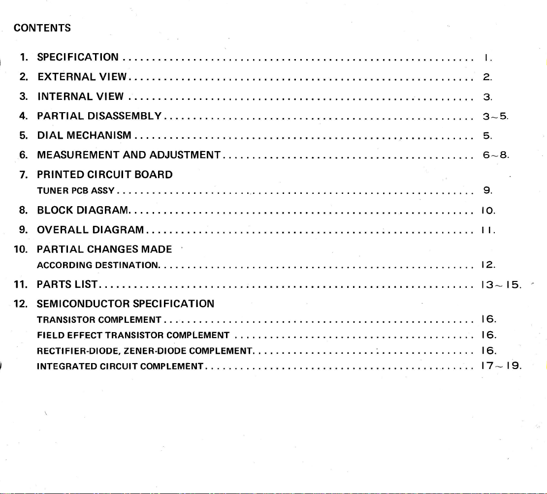
CONTENTS
1. SPECIFICATION I.
2. EXTERNAL VIEW 2.
3. INTERNAL VIEW 3.
4. PARTIAL DISASSEMBLY. 3-5.
5. DIAL MECHANISM .. . 5.
6. MEASUREMENT AND ADJUSTMENT 6-A,
7. PRINTED CIRCUIT BOARD
ftE
8.
9.
10.
TUNER PCBASSY 9.
BLOCK DIAGRAM IO.
OVERALL DIAGRAM I I.
PARTIAL CHANGES MADE
ACCORDINGDESTINATION.... 12.
PARTS LIST. t3-* t5.
SEM ICONDUCTOR SPECI FICATION
TRANSISTOR COMPLEMENT. . 16.
FIELD EFFECT TRANSISTOR COMPLEMENT . . 16.
RECTIFIER-DIODE, ZENER-DIODECOMPLEMENT.. ..... I6.
INTEGRATEDCIRCUITCoMPLEMENT.... .17_19..
11.
12.
!-.
t-
L
r
L
www.hifiengine.com
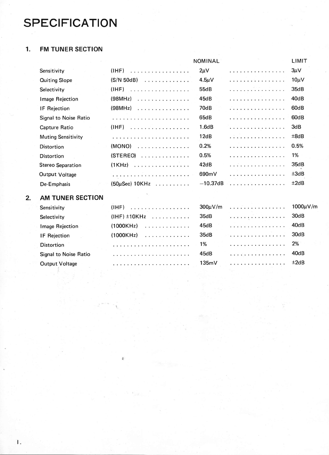
SPECIFICATION
1. FM TUNER SECTION
Sensitivity
Ouiting Slope
Selectivity
lmage Rejection
lF Rejection
Signal to Noise Ratio
Capture Ratio
Muting Sensitivity
Distortion
Distortion
Stereo Separation
Output Voltage
De-Emphasis
2. AM TUNER SECTION
Sensitivity
Selectivity
lmage Rejection
lF Rejection
Distortion
Signal to Noise Ratio
Output Voltage
(IHF)
(s/N 50dB)
(lHF)
(98MHz)
(98MHz)
(lHF)
(MONO)
(STEREO)
(1KHz)
(SOpSec) 10KHz
(tHF)
(lHF)110KHz . . .
(1000KH2)
(1000KH2)
!2dB
NOMINAL
2ttY
4.51tY
55dB
45dB
70dB
65dB
1.6dB
12dB
o.20/o
O.5o/o
42dB
690mV
-10.37dB
300pV/m
35dB
45dB
35dB
17o
45dB
135mV
LIMIT
3pV
1OpV
35dB
40dB
60dB
60dB
3dB
rSdB
O.5o/o
1o/o
3sdB
r3dB c
1000prV/m
30dB
40dB
30dB
2Vo
40dB
12dB
't
o
www.hifiengine.com
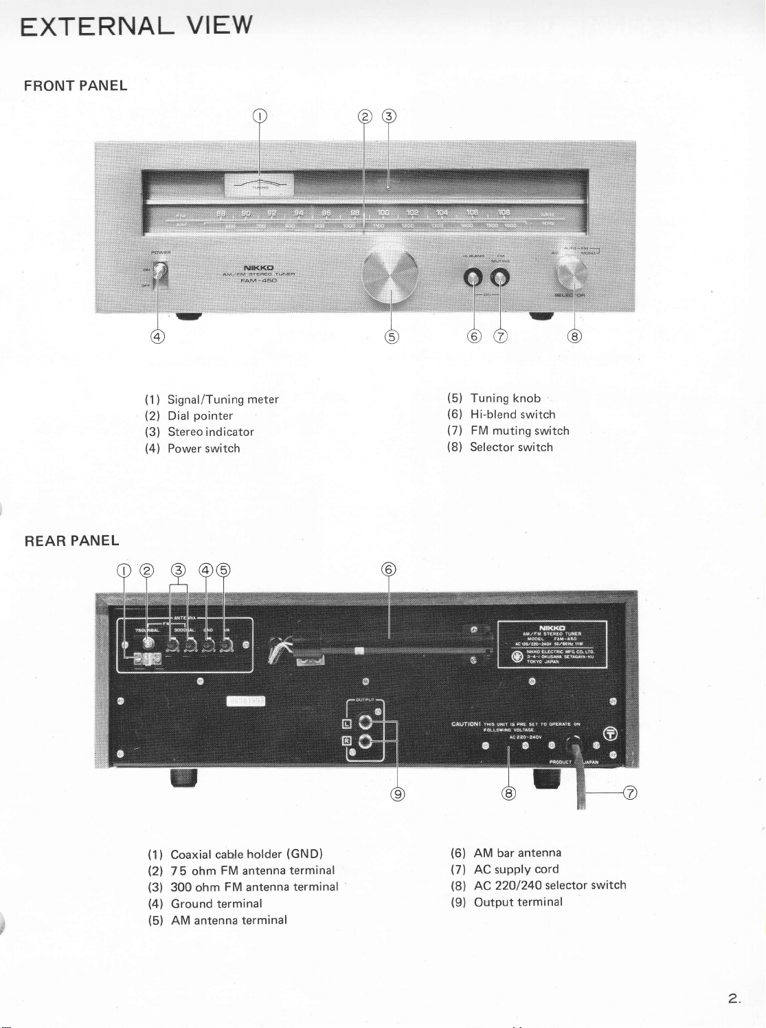
EXTERNAL VIEW
FRONT PANEL
I
v
v
(1) Signal/Tuning meter
(2) Dial pointer
(3) Stereo indicator
(4) Power switch
(5) Tuning knob .
(6) Hi-blend switch
(7) FM muting switch
(8) Selector switch
REAR PANEL
IJ
(1)
(2t
(3)
(4)
(5)
Coaxial cahle holder (GND)
7 5 ohm FM antenna terminal
300 ohm FM antenna terminal
Ground terminal
AM antenna terminal
(6) AM bar antenna
(7) AC supply cord
(8) AC 22Ol24O selector switch
(9) Output terminal
\l
2.
www.hifiengine.com
r-
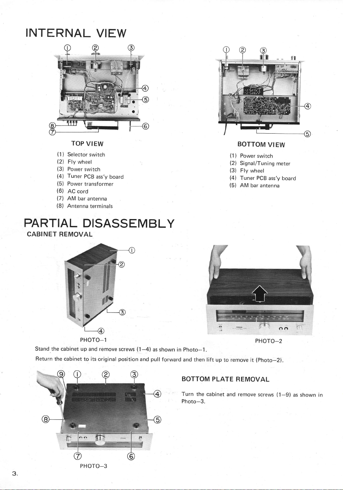
INTERNAL VIEW
TOP VIEW
Selector switch
Fly wheel
Power switch
Tuner PCB ass'y board
Power transformer
AC cord
AM bar antenna
Antenna terminals
t__
(1)
(2t
(3)
(4t
(5)
(6)
(71
(8)
(1)
(2t
(3)
(41
(5)
BOTTOM VI EW
Power switch
Signal/Tuning meter
Fly wheel
Tuner PCB ass'y board
AM bar antenna cJ
PARTIAL DISASSEMBLY
CABINET REMOVAL
PHoro-l PHOTO_2
Stand the cabinet up and remove screws (1-4) as shown in Photo-1.
Return the cabinet to its original position and pull forward and then lift upto remove it (Photo-2).
BOTTOM PLATE REMOVAL
Turn the cabinet and remove screws (1-9) as shown in
Photo-3.
r
PHOTO_1
PHOTO-3
3.
www.hifiengine.com
,YJ
'.ll.-
v
\z
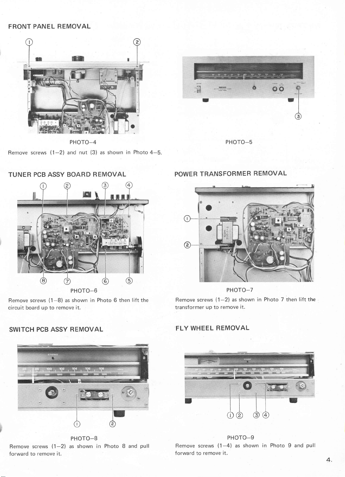
FRONT PANEL REMOVAL
PHOTO-4
Remove screws (1-2) and nut (3) as shown in Photo 4-5.
TUNER PCB ASSY BOARD REMOVAL
PHOTO_6
Remove screws (1-8) as shown in Photo 6 then lift the
circuit board up to remove it.
SWITCH PCB ASSY REMOVAL
Remove screws (1-2)
forward to remove it.
PHOTO-8
as shown in Photo 8 and pull
PHOTO_5
POWER TRANSFORMER REMOVAL
PHOTO-7
Remove screws (1-2) as shown in Photo 7 then lift the
transformer up to remove it.
FLY WHEEL REMOVAL
PHOTO-9
Remove screws (1-4) as shown in Photo 9 and pull
forward to remove it.
r
I
I
4.
www.hifiengine.com
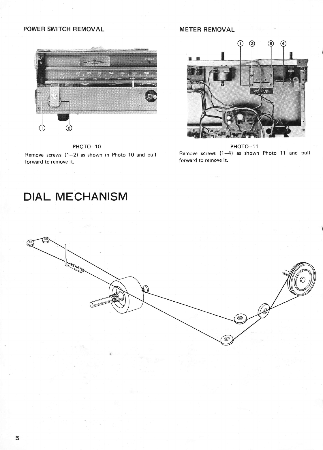
POWER SWITCH REMOVAL
PHOTO-10
Remove screws (1-21 as shown in Photo 10 and pull
forward to remove it.
DIAL MECHANISM
METER REMOVAL
PHOTO-1 1
Remove screws (1-4) as shown Photo 11 and pull
forward to remove it.
It
'vJ
5
I
.,L
\r-
U
www.hifiengine.com
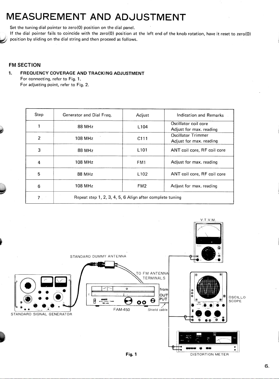
MEASUREMENT AND ADJUSTMENT
Set the tuning dial pointer to zero(0) position on the dial panel.
. lf the dial pointer fails to coincide with the zero(0) position at the left end of the knob rotation, have it reset to zero(O)
Q! oosition by sliding on the dial string and then proceed as follows.
FM SECTION
1. FREOUENCY COVERAGE AND TRACKING ADJUSTMENT
For connecting, reler to Fig. 1.
For adjusting point. refer to Fig. 2.
Step Generator and Dial Freq. Adjust lndication and Remarks
188 MHz L104 Oscillator coil core
Adjust for max. reading
2108 MHz c111 Oscillator Trimmer
Adjust for max. reading
388 MHz L101 ANT coil core, RF coil core
4108 MHz FM1 Adjust for max. reading
588 MHz L102 ANT coil core, RF coil core
b108 MHz FM2 Adjust for max. reading
7Repeat step 1, 2,3, 4,5, 6 Align after complete tuning
STANDARD DUMMY ANTENNA
FAM-450
TO FM ANTENN
TERMINALS
OSCILLO
SCOPE
lo ol
l-zfi, I
L,rrraar--l
Ltlllrlrrll
L,rr rralrrra-
I llatltl[lrtr ]
I ltttrlatrtttfl I
^ I lttrlrrf]l[ I
e lttlltrltrl I
o \4ttgtltult I
ol_ !17 _i€
to (9l
- =:-' --
a--il C o a
;aa_..
OOeo@O
OFF
ooo
c- _e-_c . cE -r#;* tt oo e
STANDARD SIGNAL GENERATOR
Fig. 1
Shield cable
DISTORTION METER
6.
www.hifiengine.com
ta
a)
2.
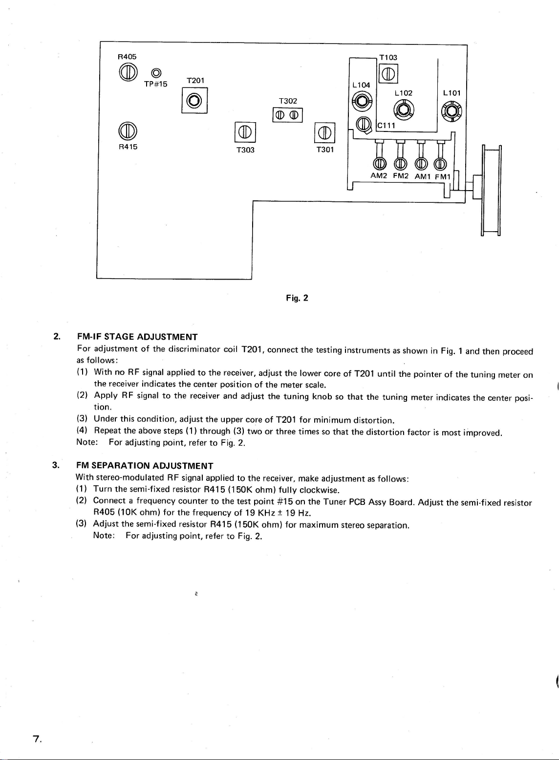
Fig.2
FM-IF STAGE ADJUSTMENT
For adjustment of the discriminator coil T2O1 , connect the testing instruments as shown in Fig. 1 and then proceed
as follows:
(1) With no RF signal applied to the receiver, adjust the lower core of T201 until the pointer of the tuning meter on
the receiver indicates the center position of the meter scale.
(2) Apply RF signal to the receiver and adjust the tuning knob so that the tuning meter indicates the center posi-
tion.
(3) Under this condition, adjust the upper core of r2o1 for minimum distortion.
(4) Repeat the above steps (1)through (3) two or three times so that the distortion factor is most improved.
Note: For adjusting point, refer to Fig. 2.
FM SEPARATION ADJUSTMENT
with stereo-modulated RF signal applied to the receiver, make adjustment as follows:
(1) Turn the semi-fixed resistor R415 (150K ohm) fully clockwise.
(2) Connect a frequency counter to the test point #1 5 on the Tuner PCB Assy Board. Adjust the semi-fixed resistor
R405 (10K ohm) for the frequency of 19 KHz t 19 Hz.
(3) Adjust the semi-f ixed resistor R415 (150K ohm) for maximum stereo separation.
Note: For adjusting point. refer to Fig. 2.
3.
t)
o
l
I
I
17.
I
I
\-
Ftu--
AM2 FM2 AMl FM1
www.hifiengine.com
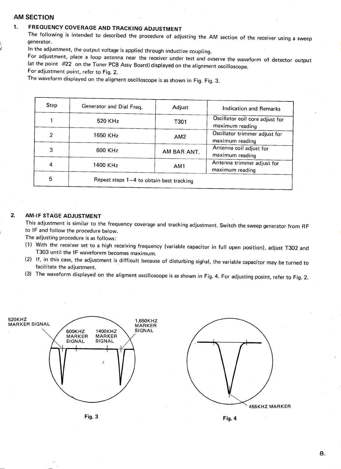
AM SECTION
1. FREOUENCV COVERAGE AND TRACKING ADJUSTMENT
The following is intended to described the procedure of adjusting the AM section of the receiver using a sweep
generator.
ln the adjustment, the output voltage is applied through inductive coupling.
For adjustment. place a loop antenna near the receiver under test and ovserve the waveform of detector output
(at the point lf22 on the Tuner PCB Assy Board)displayed on the alignment oscilloscope.
For adjustment point, refer to Fig. 2.
The waveform disprayed on the arigment oscilloscope is as shown in Fig. Fig.3.
Step Generator and Dial Freq. Adjust lndication and Remarks
152O KHz T301 Oscillator coil core adjust for
maximum reading
21650 KHz AM2 Oscillator trimmer adjust for
maximum reading
3600 KHz AM BAR ANT. Antenna coil adjust for
maximum reading
41400 KHz AMl Antenna trimmer adjust for
maximum readinq
5Repeat steps 1-4 to obtain best tracking
2. AM-IF STA.GE ADJUSTMENT
This adjustment is similar to the frequency coverage and tracking adjustment. Switch the sweep generator from RF
to lF and follow the procedure below.
The adjusting procedure is as follows:
(1) With the receiver set to a high receiving frequency (variable capacitor in full open position), adjust T302 and
T303 until the lF waveforem becomes maximum.
(21 lf , in this case, the adjustment is difficult because of disturbing sighal,
facilitate the adjustment.
(3) The waveform displayed on the aligment oscilloscope is as shown in Fig. 4. For adjusting posint, refer to Fig. 2.
the variable capacitor may be turned to
520KHZ
MARKER SIGNAL 1,650KH2
MARKER
SIGNAL
600KHZ 1400KHZ
MABKER MARKER
SIGNAL SIGNAL
Fis. 3Fig.4
8.
www.hifiengine.com
Table des matières
Autres manuels Nikko Tuner


