NF WF1973 Manuel utilisateur

MULTIFUNCTION GENERATOR
WF1973/WF1974
Instruction Manual
(Remote Control)
NF Corporation

MULTIFUNCTION GENERATOR
WF1973/WF1974
Instruction Manual
(Remote Control)
DA00016811-001

I
WF1973/WF1974
Introduction
This manual explains the WF1973/WF1974 GPIB and USB interfaces. For operations from the
panel, refer to the WF1973/WF1974 Instruction Manual.
The GPIB and USB interfaces of the WF1973/WF1974 feature a large array of functions, which
allow control of almost all front panel operations. Moreover, the setting values can be read from
outside the equipment.
●The chapter organization of the WF1973/WF1974 Instruction Manual (Remote Control) is
as follows.
1. PREPARATIONS BEFORE USE
Describes the interface settings and GPIB address settings.
2. COMMAND EXPLANATION
Outlines the commands, lists the commands, and describes the individual commands.
3. STATUS SYSTEM
Describes status reporting, including the status byte and standard event status register.
4. ERROR MESSAGES
Describes the error numbers and the error contents.
5. SPECIFICATIONS
Describes the specifications of the external control interfaces.
6. COMMAND TREE
Commands are shown in the tree structure.

II MULTIFUNCTION GENERATOR
Contents
Introduction .......................................................................................................I
Contents...........................................................................................................II
1. PREPARATIONS BEFORE USE..................................................................1
1.1 Outline of WF1973/WF1974 GPIB/USB Interface ............................................. 1
1.2 USB Preparations .............................................................................................. 1
1.3 GPIB Preparations............................................................................................. 1
1.4 Selecting the Interface ....................................................................................... 1
1.5 GPIB Address Setting........................................................................................ 3
1.6 USB ID............................................................................................................... 4
1.7 Releasing Remote Status .................................................................................. 4
1.8 Cautions............................................................................................................. 5
2. EXPLANATION OF COMMANDS.................................................................6
2.1 Outline of Commands ........................................................................................ 6
2.2 Command List.................................................................................................. 18
2.3 Description of Individual Commands ............................................................... 27
2.4 Sequence I/O Data Specifications ................................................................. 139
2.5 Trigger/Oscillation Status Control .................................................................. 142
2.6 System Unit ................................................................................................... 143
3. STATUS SYSTEM ....................................................................................144
3.1 Status Byte Register and Service Request Enable Register ......................... 144
3.2 Standard Event Status Register Group ......................................................... 145
3.3 Operation Status Register Group/Questionable Data Status
Register Group .............................................................................................. 146
3.4 Warning Event Register Group...................................................................... 154
3.5 Other.............................................................................................................. 156
4. ERROR MESSAGE ..................................................................................157
5. SPECIFICATIONS ....................................................................................160
5.1 Interface Functions ........................................................................................ 160
5.2 Response to Interface Messages .................................................................. 161
5.3 Multiline Interface Messages ......................................................................... 162
6. COMMAND TREE.....................................................................................163

1
WF1973/WF1974
1. PREPARATIONS BEFORE USE
1.1 Outline of WF1973/WF1974 GPIB/USB Interface
Almost all the functions of the WF1973/WF1974 can be remotely set via the GPIB or USB
interface. Moreover, by allowing measurement data and setting statuses to be transferred outside
the equipment, an automatic measuring system can be configured easily.
1.2 USB Preparations
The WF1973/WF1974 can be controlled by USB Test and Measurement Class (hereafter, USB-
TMC). Almost all panel operations can be controlled, and internal statuses, such as setting values
and errors, can be read out.
Install a USB-TMC class driver on the controlling computer, and connect it using a commercially
available USB cable. The installation file for this driver can be downloaded from the website of
National Instruments Corporation. The driver installation is described below.
1. Either search the VISA Run-time Engine page on the website of National Instruments
Corporation, or select “VISA driver downloads” from the following URL:http://www.ni.com/
support/visa/
2. Download VISA Run-time Engine from the VISA Run-time Engine page. User registration
is required at this time. Download Ver. 3.3 or a later version of VISA Run-time Engine.
3. The downloaded file is self-extracting. Extract and install the file.
4. Once the file has installed successfully, the USB-TMC class driver is installed.
For details, refer to the website of National Instruments Corporation.
1.3 GPIB Preparations
Install a GPIB controller board (card) in the controlling computer and connect it with a
commercially available GPIB cable. For details, refer to the user's manual of the GPIB controller
board (card) that is used.
1.4 Selecting the Interface
Either GPIB or USB can be used as the interface to be used. The WF1973/WF1974 cannot be
controlled from the interface that is not selected.
The selected interface is retained even after the power is switched off.
The USB interface is selected at shipping.
2MULTIFUNCTION GENERATOR
1. PREPARATIONS BEFORE USE
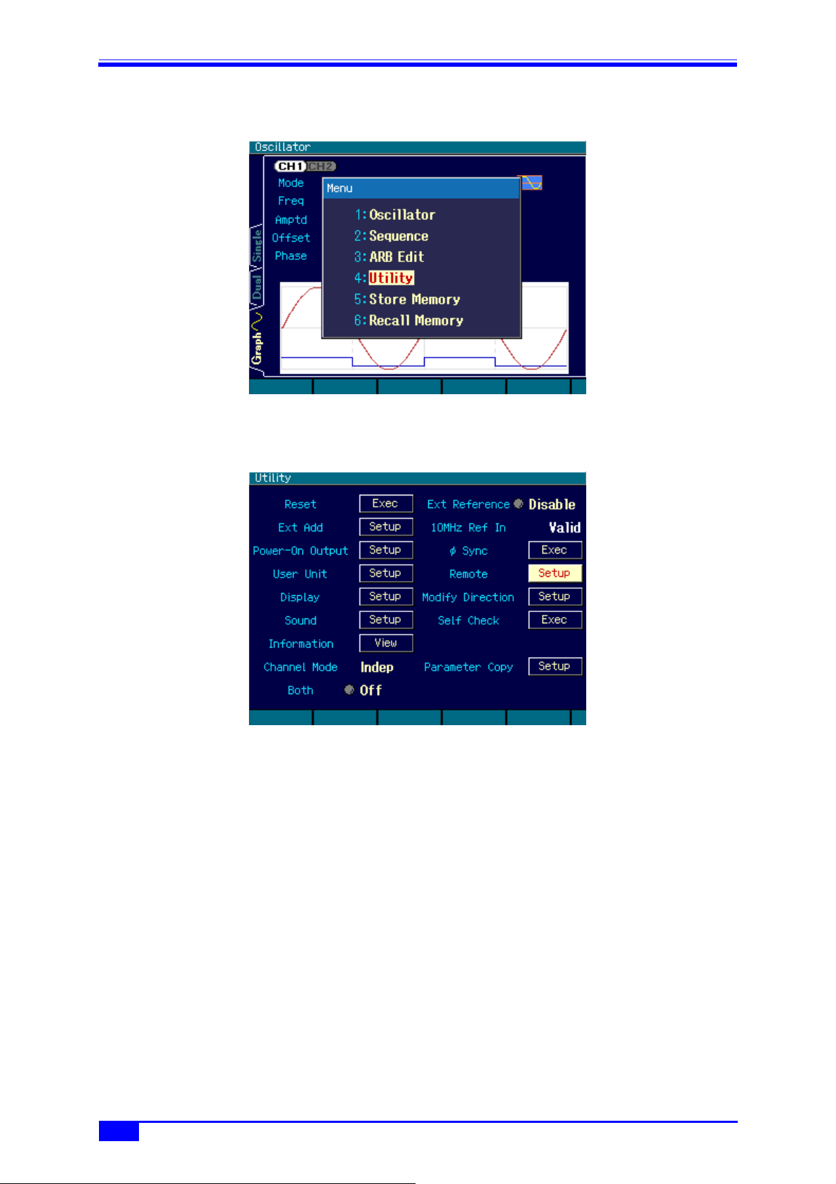
<1> From [MENU], select “4:Utility” and then press the [ENTER] key.
<2> Select “Remote” and then press the [ENTER] key.

3
WF1973/WF1974
1.5 GPIB Address Setting
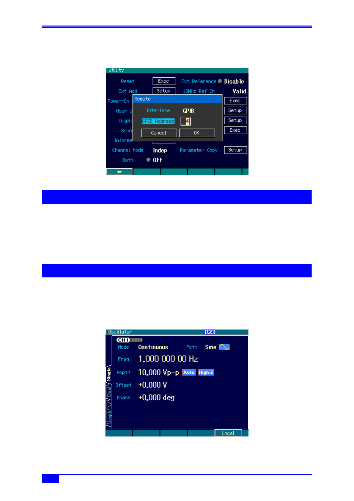
<3> Select “Interface” and then press the [ENTER] key to display the screen for selecting the
interface.
CAUTION
When the computer recognizes the WF1973/WF1974, the computer may
operate erratically when the interface is switched from USB to GPIB or the USB
cable is disconnected.
1.5 GPIB Address Setting
The GPIB address can be set.
Set the GPIB address to a different value than the addresses of other devices connected with a
GPIB cable. The set value is backed up when the power is switched off.
“2” is set at shipping.
<1> Set “Interface” to [GPIB] by performing steps <1> to <3> in “1.4 Selecting the Interface”.
4MULTIFUNCTION GENERATOR
1. PREPARATIONS BEFORE USE
<2> Select “GPIB Address” and then press the [ENTER] key to display the screen for setting the
GPIB address.
1.6 USB ID
If multiple WF1973/WF1974 units are connected within a system with USB, the following
numbers are used to allow unit recognition by the application.
• Vendor number: 3402(0x0D4A)
• Product number: 13(0x0D)/WF1973, 14(0x0E)/WF1974
• Serial number: Product’s manufacturing number (serial number)
1.7 Releasing Remote Status
In the remote control remote status, the “USB” or “GPIB” icon is lit on the LCD, and “LOCAL” is
displayed on the [F5] software key. When the [F5] key is pressed in this status, the remote status
is released, and panel operation becomes possible. However, when “LOCAL” is not displayed (local
lockout status), panel operation is disabled. To enable panel operation, specify local control from
the remote control controller.

5
WF1973/WF1974
1.8 Cautions
1.8 Cautions
• USB and GPIB connectors are located on the rear panel.
• USB and GPIB are interfaces designed based on the assumption of use in a relatively favorable
environment. Use of these interfaces in unfavorable locations such as locations with power
supply fluctuations and noisy locations should be avoided whenever possible.
• Connect/disconnect the GPIB connector only after powering off all the units connected on the
bus.
• During GPIB use, power on all the units connected on the bus.
• The total cable length should be 2 m x (number of units) or 20 m, whichever is shortest.
• The length of each cable must be 4 m max.
• Set GPIB addresses after careful checking. If the same address is set within the same sequence,
the equipment may be damaged.

6MULTIFUNCTION GENERATOR
2. EXPLANATION OF COMMANDS
2.1 Outline of Commands
The commands of the WF1973/WF1974 comply with IEEE488.2 and SCPI (version 1999.0). SCPI
defines a communication method using between controllers and measuring devices. For general
information regarding SCPI, refer to the following document:
Standard Commands for Programmable Instruments (SCPI) Version 1999.0, available at http://
www.scpiconsortium.org/.
2.1.1 Notation
For convenience, the following notation system is used in this document.
< >: < > indicates something other than the item itself. In the case of
parameters and response data, the abbreviation of the type is
enclosed in < >.
[ ]: Options, which can be omitted, are indicated between [ ].
{abc|xyz}: Means that either “abc” or “xyz” can be used.
[abc|xyz]: Indicates that either “abc” or “xyz” can be used, but that both are
options, which may be omitted.
Uppercase, lowercase: Keywords in both uppercase and lowercase are the long form,
while keywords in uppercase only are the short form.
2.1.2 Commands
The program messages of the WF1973/WF1974 are configured of common commands and
subsystem commands.
The format of each type of command, the subsystem command tree, etc., are described
below.
2.1.2.1 Common commands
Common commands are commands that are used to control comprehensive functions of the
equipment.
Figure 2.1 shows the common command syntax.
Figure 2.1. Common Command Syntax
The keyword in Figure 2.1 consists of 3 alphabetic characters. Here, SP is a space character
(ASCII code 32).
ParameterKeyword SP
?
Autres manuels pour WF1973
1
Ce manuel convient aux modèles suivants
1
Table des matières
Autres manuels NF Générateur portable


