Neware CE-6000n Manuel utilisateur

1
User Manual
CE-6000n power battery test equipment
Attention
PLEASE:
Read the User Manual before operating
Preserve the User Manual.
Read carefully for safety matters.
Manufacturer: Neware Technology Limited
Address: 15/F, Tower 3, Excellence City, No, 128 Zhongkang Rd,
Shenzhen, China, 518049
Tel: 0755-83108866
Website: http://www.newarebattery.com

User Manual
2
Neware Technology Limited
http://www.newarebattery.com
Catalog
Welcome...........................................................................................................................................................3
Chapter 1. Inspection............................................................................................................................... 6
Chapter 2. Installation..............................................................................................................................7
2.1 Appearance..............................................................................................................................7
2.2 Installation of Cabinet.............................................................................................................8
2.3 Electric connection............................................................................................................. 10
2.4 Installation Tools.................................................................................................................15
Operation......................................................................................................................................................16
Chapter 3. Safety Notice......................................................................................................................16
3.2 Safety Requirements for operate technician.......................................................................17
3.3 Marking Requirements....................................................................................................... 17
3.4 Safety Warning Requirements............................................................................................ 17
After the installation, be sure you lock the cabinet door and keep the keys safely.................... 18
3.5 Fire Entrance Requirements............................................................................................... 18
3.6 Battery safety requirements................................................................................................18
3.7 Installation requirements.................................................................................................... 18
Grounding requirements.............................................................................................................. 18
3.9 Power-off Operation Requirements....................................................................................19
3.10 Scrap Requirements.......................................................................................................... 19
3.11 Other Protection Requirements.........................................................................................19
Chapter 4. Equipment Introduction..................................................................................................... 19
4.1 System composition............................................................................................................20
4.2 System topology................................................................................................................. 21
4.3 Specification....................................................................................................................... 22
Chapter 5. Touch Screen Description.................................................................................................. 26
5.1 Home page.......................................................................................................................... 26
5.2 Overview.............................................................................................................................27
5.3 Setting................................................................................................................................. 28
5.4 Switch machine...................................................................................................................29
5.5 Operating data.....................................................................................................................30
5.6 Fault record......................................................................................................................... 31
5.7 Automatic calibration..........................................................................................................32
6.1 Power on............................................................................................................................. 34
6.2 Power off.............................................................................................................................34
Chapter 7. Maintenance....................................................................................................................... 35
7.3 Clean maintenance..............................................................................................................36
7.4 Torque requirements........................................................................................................... 36
Chapter 8. Repairing............................................................................................................................ 36
8.1 Recovering of fault operation.............................................................................................36
8.2 Common faults....................................................................................................................37

User Manual
3
Neware Technology Limited
http://www.newarebattery.com
Welcome
Thank you for choosing Neware. We offer quality production and reliable after-sales service
to you.
To ensure the safe operation and the functionality of the equipment, please read this user
Manual carefully before operation.
This manual will introduce the fundamental theory, standard, construction, norms of operation,
maintenance, trouble-shooting for potential faults, and electrical diagram. Any "test
regulation" standards that were mentioned in this menu were for reference only. If you have
any objections, please consult the relevant standard-document or research materials.
This manual is intended to instruct the user to properly operate the equipment. Please read
carefully.
Liabilities
Neware is not responsible for the damage that results from negligence or fault operations that
are not caused by Neware. Please follow this "user manual" to avoid potential negligence or
fault.
Attention
Keep the manual.
Ask for a replacement if any errors in this manual are found.
Constitute:
This manual is consisted from 4 parts for potential needs.
Name
Content
Welcome
The description of this manual and the general description of the
equipment.
Installation
Related installation operations include solutions for installation, setup, and
moving.
Operation
Introduction to the equipment's fundamental operation methods, and related
troubleshooting for problems that you might encounter.
Reference
Relevant references to this equipment.

User Manual
4
Neware Technology Limited
http://www.newarebattery.com
Statement of Safety Symbols:
The symbols below will be indicated in this manual.
Danger
A faulty operation can result in serious harm. Do not operate the equipment
under this condition.
Warning
A faulty operation can result in a minor injury. Additionally, equipment or
test samples will be damaged.
Attention
Utility or damage prevention indicator.
Keywords:
Steps: operation command
Reference: information for reference
Description of test equipment’s relevant information:
The naming of this equipment is based on the series, the quantity of the channels, the level of
voltage/current, the type of charge/discharge port, and the optional negative voltage.
Please check the nameplate on the equipment to confirm the model type.
This manual will include all the models of CE-6000 series equipment. You will be
only responsible for reading about the specific model that you purchase.
Model
CE-60XXn
-
120V
50A
-B
Sign
①
②
③
④
Means
①
Power battery test equipment, XX stands for quantity
of channels (e.g. CE-6002n stands for two
channels, CE-6012n stands for 12 channels).
②
Output voltage
③
Output current for a single channel
④
-B: separated charge and discharge ports
-F: negative voltage available
(Hint: Standard equipment came without ④)

User Manual
5
Neware Technology Limited
http://www.newarebattery.com
Installation
CE-6000n power battery test equipment
Attention
This chapter states the installation method of the equipment.
Read this chapter if you need to move the equipment.
Users must read this chapter no matter whoever is responsible for
installation.

User Manual
6
Neware Technology Limited
http://www.newarebattery.com
Chapter 1. Inspection
Check the items according to the "Packing List" and confirm that all the required items were
sent.
If you have any special orders, please check the "Packing List" to confirm.
Contact the supplier (Neware) if there is any loss or damage.
Notice: A "Packing List" will be shipped with the equipment.

User Manual
7
Neware Technology Limited
http://www.newarebattery.com
Chapter 2. Installation
This chapter introduces the appearance of the equipment and the required conditions for
installation.
2.1 Appearance
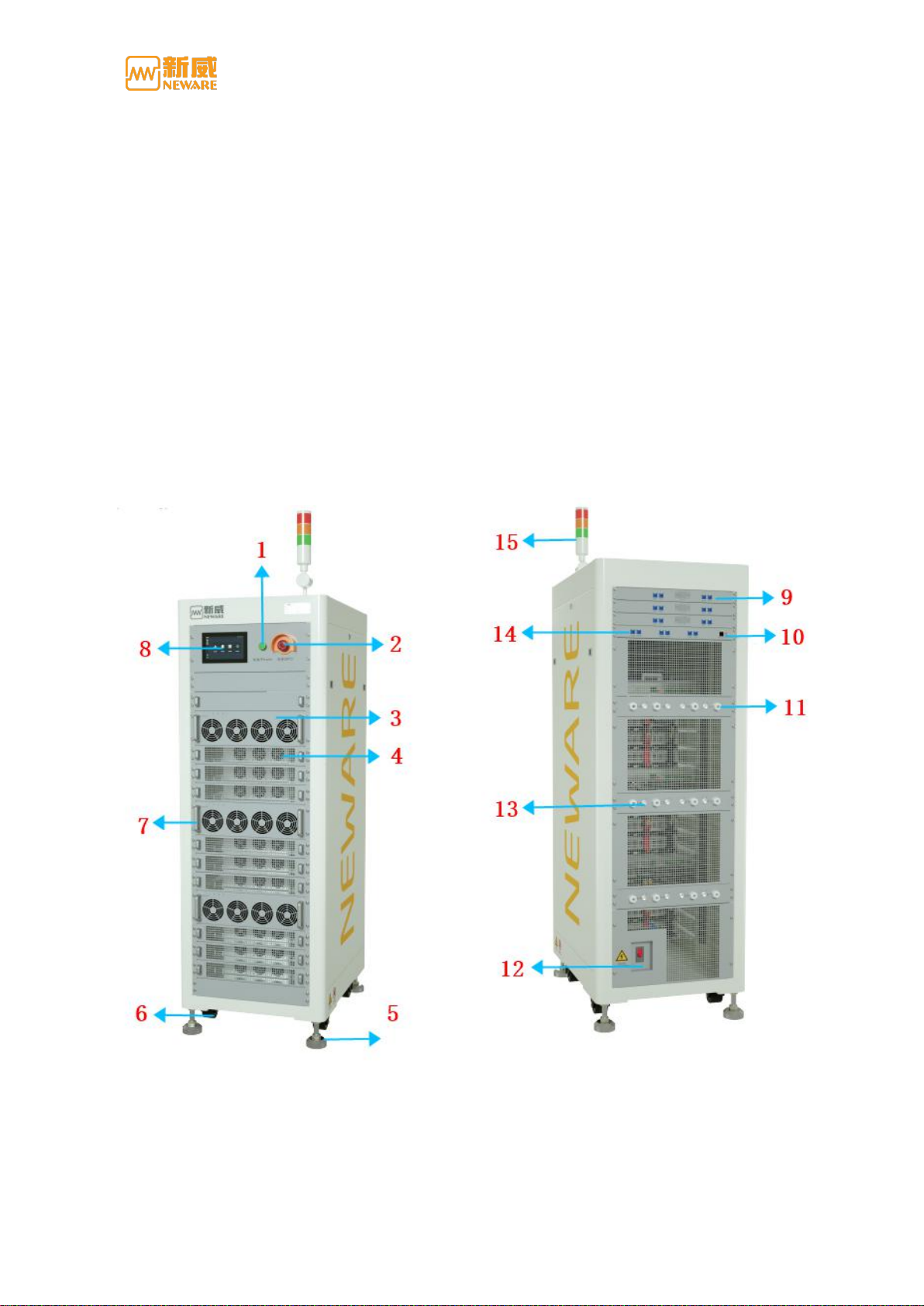
Front
Back
Appearance Figure(For reference only)

User Manual
8
Neware Technology Limited
http://www.newarebattery.com
NO.
Name
Functions/Usage
1
Indicator
Operation indicator
2
Stop button
Emergency protection
3
AC/DC Module
AD input to DC output
4
DC/AC Module
DC input to AC output
5
Footing
For equipment positioning
6
Caster
For short distance moving
7
Handle
For installation
8
Screen
Man-computer interaction interface
9
Net port
BMS communication port
10
Net port
Network communication port
11
Output channel cable
Channel cable for batteries connection
12
Breaker
On/Off switch of power supply
13
Battery voltage
sampling port
Sampling the voltage of the connected battery
14
Net port
For Auxiliary connection
15
Warning light
Reflect ON working conditions
2.2 Installation of Cabinet
Site configuration
This part indicates the spatial requirements for the equipment to ensure safe operation.
■Site requirement for installation
The equipment is required to be setup on the floor with flame-proof material, and the
flooring is constructed with the U-bar. The floor is required to be flat and firm enough
to support the weight of the equipment.
Adequate ventilation and no direct sunlight.
Temperature:-10°C~40°C, no rapid temperature change.
Humidity: 5%-95%RH
Altitude: <2000
No high-density dust, no flammable or corrosive components around the equipment.
■Storage/Operating space

User Manual
9
Neware Technology Limited
http://www.newarebattery.com
This equipment is designed for in-door usage.
Safety-level-IP20. Equipment is required to be set up on a flat concrete floor or on a setting
plate that can support the weight of the equipment. It is suggested to setup an air purification
treatment to reduce the effect of the dust.
The air intake is supposed to keep a distance from any closed objects to ensure sufficient
ventilation. It is recommended to set up a ventilation device that can control the temperature
in the workplace to ensure the long-term reliability of the equipment,
Sufficient space (> 600mm) between testers and walls to ensure ventilation and escape space.
Sufficient space (> 500mm) above the equipment for ventilation, maintenance, and operation.
■Wire trough requirement
The network cable and power cable should be placed separately to reduce EMI from the
power circuit to the network communicator.
■Moving
This equipment is available for transport by forklift or tray carriage. Check the weight of the
equipment and the correct support point for safety purposes.
The forklift is the best transporter for this equipment. The gravity centre of the cabinet is
required to be set between the fork arms, and it is suggested to do a test lift. Make sure all the
operations are slow and stable. Please place it on the firm and stable floor, and follow the
safety operation process.
Warning
Use a forklift with the proper size and elevating capacity to move the equipment. Jack
the equipment from the bottom. The cabinet must be secured from slipping when
jacking up.

User Manual
10
Neware Technology Limited
http://www.newarebattery.com
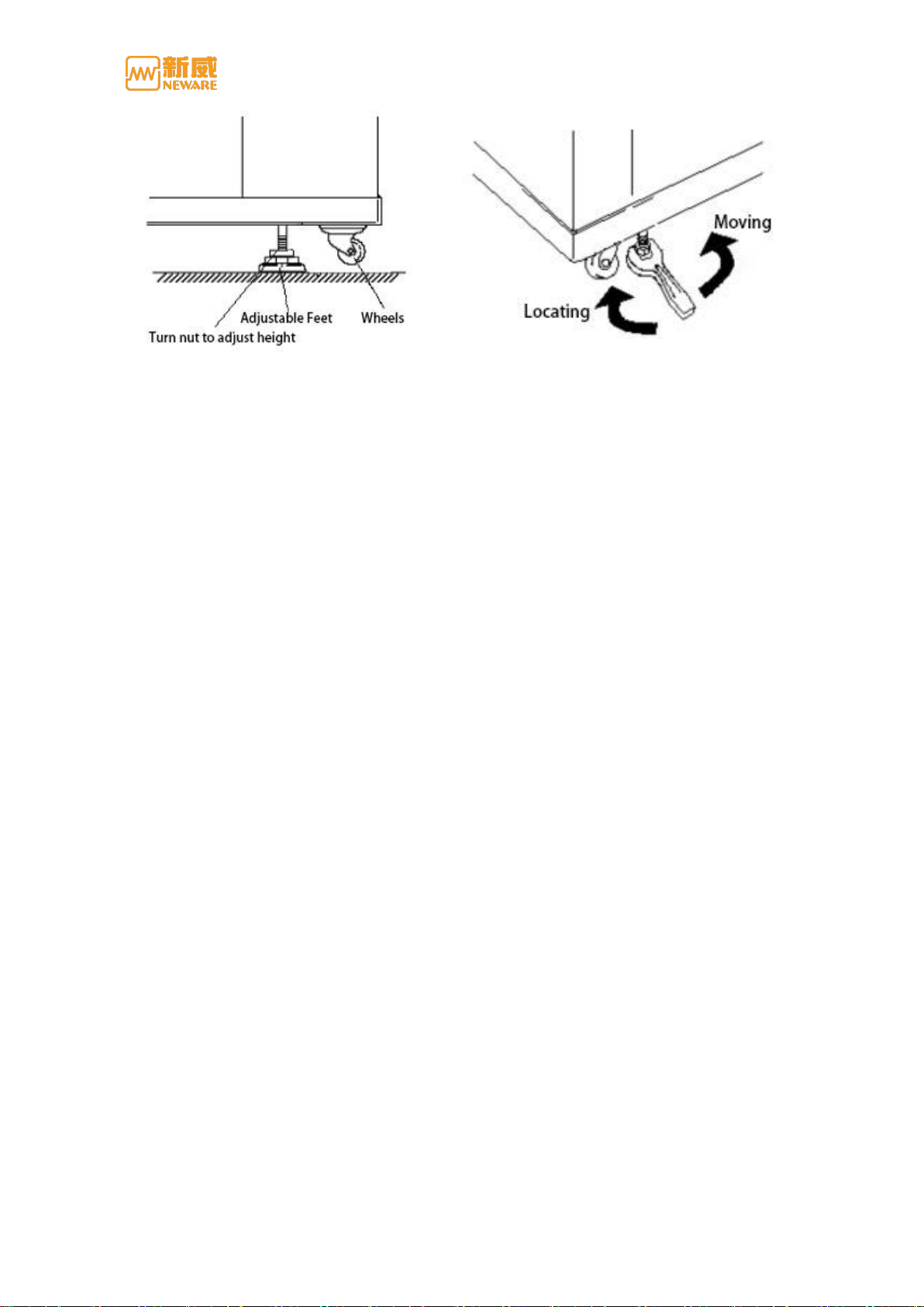
Adjustable feet (optional) are located on each corner at the bottom of the equipment. The
height of the adjustable feet is adjusted by tightening or loosening the nut with a wrench.
Adjusting the nut in a clockwise direction will lift the wheels off the floor and the equipment
will stand firmly on the floor. Adjusting the nut in a counter-clockwise direction will let the
wheels connect to the floor, making the equipment moveable.
2.3 Electric connection
Wires for required connections:
Ground wire
DC side cable
AC side cable
Communication cable
Requirement for Cable
All the cables required a sufficient current-carrying capability. The current-carrying
capability will be affected by the environmental conditions, insulating materials,
method of laying, materials of wire, and cross sectional area.
All the cables must based on the maximum AC current and reserve some retained
current.
All the cables on the same side must have the same parameters and form.
The cable must be flame-proofed.
Table des matières
Autres manuels Neware Équipement de test
Manuels Équipement de test populaires d'autres marques

SMART
SMART KANAAD SBT XTREME 3G Series Manuel utilisateur

Agilent Technologies
Agilent Technologies BERT Serial Manuel utilisateur

Agilent Technologies
Agilent Technologies N3280A Manuel utilisateur

Vernier
Vernier Go Direct Voltage Manuel utilisateur

Lifeloc
Lifeloc R.A.D.A.R. Manuel utilisateur

Fluke
Fluke T5-600 Instructions d'utilisation et d'installation