
netvox Z809A Manuel utilisateur

ZigBeeTM- Measurement and Switch Socket
User Manual
Measurement and Switch Socket
Model: Z809A
Firmware: V3.5
Hardware: V1.2

1
Table of Contents
1. Introduction.............................................................................................................................................................. 2
2. Product Appearance.................................................................................................................................................2
3. Specification.............................................................................................................................................................. 3
4. Installation.................................................................................................................................................................4
5. Setting up Z809A...................................................................................................................................................... 4
5-1. Join the ZigBee Network................................................................................................................................ 4
5-2. Permit-Join...................................................................................................................................................... 4
5-3. Binding............................................................................................................................................................4
5-4. Control.............................................................................................................................................................5
5-5. Reset Power Consumption Summation.......................................................................................................... 5
5-6. Restore to Factory Setting...............................................................................................................................5
5-7. Power Metering...............................................................................................................................................5
5-8. Report Configuration for Developer Only......................................................................................................6
6. Home Automation Clusters for Z809A.................................................................................................................. 8
7. Netvox App Control Interface.................................................................................................................................9
8. Loading property....................................................................................................................................................12
9. Important Maintenance Instructions................................................................................................................... 13
2
1. Introduction
Netvox Z809A, a ZigBee measurement and switch socket, acts as a Router Device in ZigBee network. It performs
the On/Off controlling feature. Users are able to wirelessly control the switch through paired soft On/Off button or
paired remote controller. Users could also monitor the power consumptions such as current/ voltage/ power/ energy
through Netvox ZiG-BUTLER application.
What is ZigBee?
ZigBee is a short range wireless transmission technology based on IEEE802.15.4 standard and supports multiple
network topologies such as point-to-point, point-to-multipoint, and mesh networks. It is defined for a
general-purpose, cost-effective, low-power-consumption, low-data-rate, and easy-to-install wireless solution for
industrial control, embedded sensing, medical data collection, smoke and intruder warning, building automation
and home automation, etc.
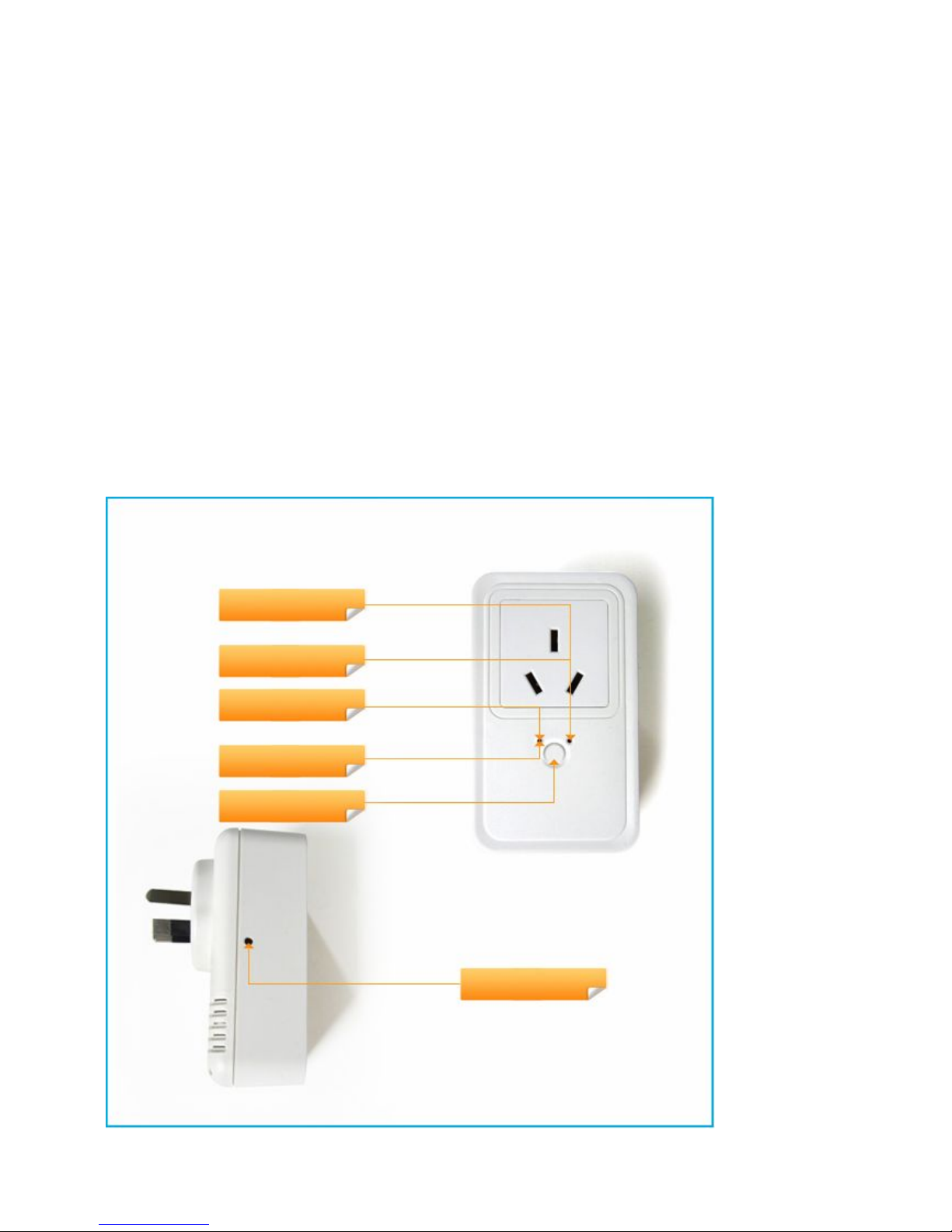
2. Product Appearance
On/Off Status Indicator (Red)
On/Off Status Indicator (Green)
Network Indicator (Red)
Network Indicator (Green)
Switch Key
Binding Key

3
Socket/Plug Selection
3. Specification
Fully IEEE 802.15.4 compliant
Utilizes 2.4GHz ISM band; up to 16 channels
Power supply: 100~240VAC; 50/60Hz
Power consumption: 15mA@220V
Resistive load: 250VAC/ 16A
Inductive load: 220VAC/ 8A
Monitoring range 100mA to 16A with ±1% accuracy
Relay lifetime: 100,000 times
Up to 210 meters wireless transmission range in non-obstacle space
Easy installation and configuration

4
4. Installation
This device is NOT truly waterproof/ resistant and is for indoor use.
Power on Z809A using 100~240 VAC power supply. All the indicators will flash once.
5. Setting up Z809A
5-1. Join the ZigBee Network
After Z809A is turned on (all indicators flash once), it will search for an existing ZigBee network and send a
request to join the network automatically. While Z809A is under the coverage from a coordinator or a router
whose permit-join feature is enabled, Z809A will be permitted to join the network.
A. Before Z809A is joined a ZigBee network → the network indicator will stay off.
B. After Z809A has joined a ZigBee network → the network indicator will stay green.
5-2. Permit-Join
Z809A is designed to work as a router. To allow other devices to join the ZigBee network, users could enable
the Permit-Join feature using the tips:
A. Press the Binding Key to enable the Permit-Join feature. The network indicator will flash green per
second.
B. The default Permit-Join period of time is 60 seconds.
Z809A allows up to 14 End Devices to join its network.
5-3. Binding
Z809A can be bound with the device which supports On/Off cluster (such as Netvox Z501 or client devices
which are carrying meter cluster).
Step1. Press and hold the Binding Key for 3 seconds.
Step2. Release the Binding Key when the network indicator flashes green once.
Step3. Enable the binding feature of the On/Off device.
Step4. The network indicator flashes green 5 times after the binding is completed; otherwise, it will
flash green 10 times.

5
5-4. Control
A. Remote Control
Users are able to use the device which is bound with Z809A to control it.
While the switch is ON, the On/Off Status Indicator shows green.
While the switch is OFF, the On/Off Status Indicator shows red.
B. Switch Key Control
Users also can control Z809A via the Switch Key.
5-5. Reset Power Consumption Summation
To reset the power consumption data, please follow the steps:
Step1. Press and hold the Binding Key for 20 seconds. The network indicator will flash green 4 times (at
the 3rd, the 10th, the 15th, and the 20th second).
Step2. After releasing the Binding Key, press the Switch Key within 2 seconds. The network indicator
will flash green once.
5-6. Restore to Factory Setting
To restore it to factory setting, please follow the steps:
Step1. Press and hold the Binding Key for 15 seconds. The network indicator will flash green 3 times (at
the 3rd, the 10th, and the 15th second).
Step2. After releasing the Binding Key, press the Switch Key within 2 seconds. The network indicator
will rapidly flash green.
Step3. After fast flashes, Z809A will reboot, and the restore is completed.
5-7. Power Metering
Z809A reports the power consumption data to the ZigBee network.
The related Cluster ID:
Simple Metering Cluster ID (0x0702)
Electrical Measurement Cluster ID (0x0B04)
The related Attribute ID of Simple Metering Cluster ID:
Current Attribute ID: 0xE000; unit: mA
Voltage Attribute ID: 0xE001; unit: V
Power Attribute ID: 0xE002; unit: W
Energy Attribute ID: 0xE003; related to AttributeID CurrentSummationDeliver (0x0000); unit: Wh
6
The related Attribute ID of Electrical Measurement Cluster ID:
Current Attribute ID: 0x0508
Voltage Attribute ID: 0x0505
Power Attribute ID: 0x050B
Power Factor Attribute ID: 0x0510
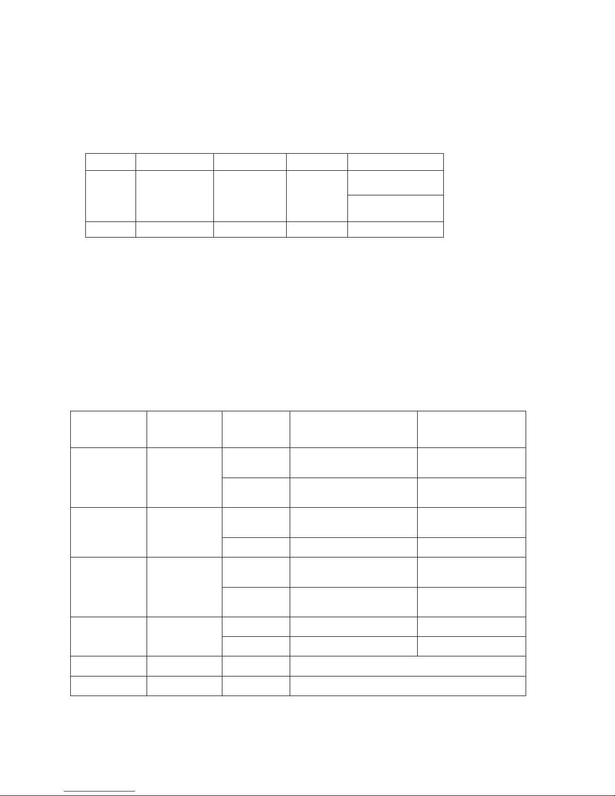
The command to reset power consumption summation: 0xE0. The format is:
Bits:8 16 8 8 8
Frame
control
Manufacturer
code
Transaction
Sequence
number
Command
identifer
Frame payload
Action
0x05 0x109F 0xe0 0x00
(clusterid:0x0702,Action:0x00)
5-8. Report Configuration for Developer Only
After the device receives ConfiugreReport (Max! = 0xFFFF) command, if the configuration is successful, it will
immediately issue a Report command and then it will report according to report setting.
After powering on, Z809A will detect battery voltage, if the device report has been previously configured, it will
issue 1 or 2 reports within 1-60 seconds randomly on the device, and thereafter it will report according to the
configuration.
Report setting table:
Min Interval
(Unit:second)
Max Interval
(Unit:second)
Reportable
Change
Change rate≥ Reportable
Change
Change rate<
Reportable Change
1-65534 1-65534
≠0To report per Minimum
interval
To report per Maximum
interval
0To report per Minimum
interval
To report per Minimum
interval
0 1-65534
≠0 To report instantly To report per Maximum
interval
0 To report per second To report per second
1-65534 0
≠0To report per Minimum
interval No report
0To report per Minimum
interval
To report per Minimum
interval
0 0
≠0 To report instantly No report
0 To report per second To report per second
Any 65535 Any Stop reporting
65535 Any Any Stop reporting
Note:(1) It is not suggested to set:
Min Interval =0,

7
Reportable Change=0.
Otherwise, Z502B will report very densely to block up the network.
(2) Different attributes have different units, please refer to the product specific
instructions for units of reportable change.
6. Home Automation Clusters for Z809A
A cluster is a set of related attributes and commands which are grouped together to provide a specific function. A
simple example of a cluster would be the On/Off cluster which defines how an on/off switch behaves. This table
lists the clusters which are supported by Z809A.
1.End Point(s):0x01
2.Device ID:Mains Power Outlet (0009)
3.EndPoint Cluster ID
Attributes of the Basic Device Information attribute set
Identifier Name Type Range Access Default Mandatory
/ Optional
0x0000 ZCLVersion 8-bit
Unsigned
integer
0x00 –0xff Read
only
0x03 M
0x0001 ApplicationVersion 8-bit
Unsigned
integer
0x00 –0xff Read
only
0x21 O
Cluster ID for Z-809A
Server side Client side
EP 0x01 Mains Power Outlet (0009)
Basic(0x0000)None
Identify (0x0003)
Groups (0x0004)
Scenes (0x0005)
On/Off (0x0006)
Diagnostics(0x0B05)
Commission(0x0015)
Electrical Measurement (0x0B04)
Simple Metering(0x0702)

8
Identifier Name Type Range Access Default Mandatory
/ Optional
0x0002 StackVersion 8-bit
Unsigned
integer
0x00 –0xff Read
only
0x35 O
0x0003 HWVersion 8-bit
Unsigned
integer
0x00 –0xff Read
only
0x0C O
0x0004 ManufacturerName Character
string
0 – 32
Bytes
Read
only
netvox O
0x0005 ModelIdentifier Character
string
0 – 32bytes Read
only
Z-809AE3
R
O
0x0006 DateCode Character
string
0 – 16 bytes Read
only
20141020 O
0x0007 PowerSource 8-bit
Enumeration
0x00 –0xff Read
only
0x01 M
7. Netvox App Control Interface
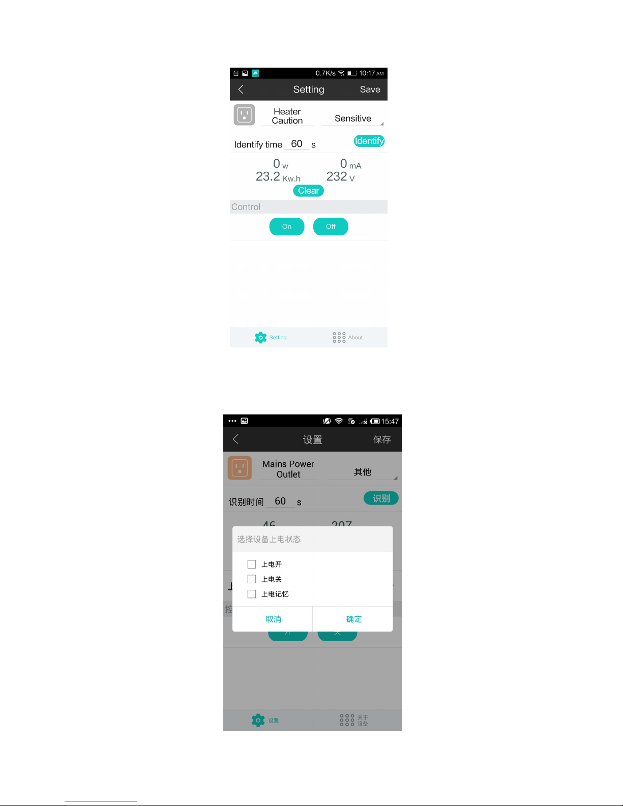
1. After joining in Netvox App system, device IEEE address will show up in device management interface. Select
“Mains Power Outlet”; there is only an EP as below:
9
2. Select “Mains Power Outlet” to enter setting interface. Click “bind device” as below:
3. Click “Power Status” as below:
Table des matières
Autres manuels netvox Domotique


