NAVTELECOM SMART S-2433 Manuel utilisateur

GPS/GLONASS TRACKING EQUIPMENT
SMART S-2433
Operations manual
Installation and connection of the device
v1.0
MOSCOW
2020

Dear customer!
This Operations manual provides information about main issues relating to the functioning, installation, and operation
of the device.
Customers are strongly advised to study this document carefully before the installation and operation of the device.
Navtelecom LLC is interested in constantly improvement of the manufactured products quality.
Please, contact our technical support by email address: [email protected] should you have any questions or
problems with the device.
It is possible to download software, documentation and get detailed information on the manufacturer's website
https://navtelecom.ru.en
We thank you for purchasing of our product! We are sure that if operation of the equipment is correct, it will reliably
serve you for a long time.

CONTENTS
CONTENTS ........................................................................................................................................... 2
1. BASIC CHARACTERISTICS ............................................................................................................ 3
1.1 Purpose of the system ............................................................................................................. 3
1.2 System tasks............................................................................................................................ 3
1.3 Operational principles ............................................................................................................. 3
1.4 Basic technical characteristics ................................................................................................ 4
1.5 Appearance of the device ........................................................................................................ 6
1.6 Standard equipment set .......................................................................................................... 7
1.7. Device components ................................................................................................................ 9
1.8 Device interface connector.................................................................................................... 11
2. DEVICE CONNECTON................................................................................................................... 12
2.1 Installation ............................................................................................................................ 12
2.2 SIM-card installation and operation ..................................................................................... 13
2.3 Power connection .................................................................................................................. 13
2.4 Universal inputs connection .................................................................................................. 14
2.4.1 Analog sensors connection.............................................................................................. 14
2.4.2 Discrete sensors connection ........................................................................................... 14
2.4.3 Pulse frequency sensors connection ............................................................................... 16
2.5 Built-in accelerometer ........................................................................................................... 17
2.6 Control outputs connection ................................................................................................... 18
2.7 1-Wire informational interface (IButton) connection........................................................... 20
2.8 RS-232 interface connection ................................................................................................. 22
2.9 RS-485 interface connection ................................................................................................. 22
3. LED INDICATION......................................................................................................................... 24

1. BASIC CHARACTERISTICS
1.1 Purpose of the system
The equipment is a GPS-GSM Based Vehicle Tracking System. It is allowed to use the following terms in relation to this
device: “system”, “product”, “equipment”, “device” “terminal”, “tracker”.
The system is designed for:
vehicle monitoring: its location, track, mileage, fuel consumption, engine hours;
driving style determination (EcoDriving);
crush event fixation in accordance with acceleration thresholds or Addiction Severity Index (ASI);
emergency informing about vehicle hijacking;
emergency informing about attacks on the driver or passengers and other accidents;
processing and transmitting of data to the server from devices such as tachograph, tire pressure monitoring system,
CAN bus adapter, refrigerator controller, RFID tag reader;
monitoring the temperature using temperature sensors;
remote control of connected devices and vehicle systems, such as a siren, engine and door lock system, etc.
Recipients of information from the system can be:
centralized dispatch centers;
end-users (corporate and private car owners, proxy persons, etc.)
1.2 System tasks
The system operation consists of the following tasks:
telemetering record of vehicle location, speed, direction and mileage according to the GPS/GLONASS satellite
information;
telemetering record from the contact, impulse, analog connected sensors and CAN bus; monitoring of vehicle
battery voltage and device built-in battery voltage;
fuel consumption, drains and fills monitoring; mileage monitoring; stoppage time and off-track monitoring; places
of cargo loading/unloading monitoring;
events data record to the nonvolatile memory, possibility of its remote reading and analyzing;
sustained or specified time period transmission of information about current and past events on the vehicle via
GPRS-channel to the telematics server for further analyzing, visualization and report formation;
customer SMS informing on sensors activation;
connected external devices control (for example, siren on/off) by SMS command or by preset settings in automatic
mode;
control of cargo safety by comprehensive measures; improving driver and passenger’s safety.
1.3 Operational principles
The device during its operation continuously monitors the status of the connected sensors, vehicle battery voltage,
built-in device battery voltage, GSM modem signal level, operational capability of navigational sensor (GPS/GLONASS), etc.
At power-up or USB connection to a computer the device automatically turns on. At power-off or USB disconnection
the device continues its operation from built-in battery. The device turns off when the built-in battery is discharged to 3V.
Upon the occurrence of an event set by the device logic (set by the user or device manufacturer), the telematics
information is recorded into nonvolatile memory and is sent to tracking platform as a message with a set of parameters.
Events for messages formation can be change of direction, timer activation in motion or in stand, activation of input sensor,
value changes of analog or digital sensor, etc. Each message is recorded with its sequence number and has its own code
that determines the reason for its formation. When sending message packets after reconnecting to tracking platform, the
earlier messages are sent first. Some messages generated by “alarm” events (pressing the panic button, impact sensor
detection, etc.) are sent out of turn, immediately after the “alarm” event has happened. After message packet sending to
the server, the device is waiting for server answering. If there is no answering from the server, the device will try to send
message again until it receives answering about data transferred, in this case the next packets from the queue will not be
sent. This algorithm set in the data transfer protocol ensures reliable sending of all messages to the server, even in case
of data transmitting failure.
The device operation parameters are configured using proprietary software, the NTC Configurator program. For
proper software operation there is a requirement for a computer with MS Windows 7 or higher operating system.
It is also possible to perform basic settings via Bluetooth, USB, GSM channels using the NTC Control program - a
mobile application for smartphones and tablets running the Android operating system.

1.4 Basic technical characteristics
Tab 1
S-2433
GSM/GPRS/Bluetooth
GSM frequency bands
GSM 850, EGSM 900, DCS 1800, PCS
1900
GPRS class
B, multislot class 12
Transmitter power
Class 4 (2W) в GSM 850 и EGSM 900;
Class 1 (1W) в DCS 1800 и PCS 1900
Maximum speed of data transfer/reception, kbit/s
85,6
SIM card holder 1
external with the plug, miniSIM
SIM card holder 2
no
SIM chip1
no
GSM-signal jammer detector
yes
Bluetooth
yes, v 4.0
GNSS
Supported navigation systems
GLONASS/GPS/Galileo/QZSS
Number of channels
tracking: 33, Figureking-up: 99
Sensitivity (in laboratory conditions)
tracking: -166 dBm
cold start: -148 dBm
Time of first coordinates determination (for GPS and GLONASS systems with
a signal of -130 dBm)
cold start: 29 sec
warm start: 22 sec
hot start: <1 sec
Coordinates error, (50% CEP, 24 hours in static mode, with
signal levels -130 dBm), m
2.5 (in plan), 5 (in height)
Coordinate update rate, Hz
1
GNSS jammer detector
yes
Power supply
Operation supply voltage, V2
9,5…47
Current consumption at 12 V voltage in operation mode on
average3, mA
80
Current consumption at 12 V voltage with turned off
GLONASS and GSM modules is no more than, mA
25
Maximum current consumption at 12 V voltage in the operation with the
charge of the battery is not more than, mA
200
Protection against polarity reversal
yes
Protection against prolonged overvoltage up to 500 V
yes
Battery4
Li-Po 3,7 V, at least 800 mAh
Battery protection from recharge, full discharge, short circuit5
yes
Maximum operating time of the device from the fully charged battery
(without external power) is at least, h
6
Time of full charge of the battery is not more than, h
5
Quartz crystal unit
yes
Backup battery of the RTC clock and the navigation module
yes
Time of keeping of the RTC clock rate and ephemeris in a navigation module
(with the power off and discharging of the battery) is at least, days
5
Battery charging from USB
yes
Interfaces/sensors
Inputs against power surges, V
up to 350
Total number of universal (analog, discrete, pulse-frequency) inputs
3
Built-in pull-up resistor for discrete or pulse-frequency inputs
yes
Measuring range by inputs, set up as analog, V
0…31

Working range with frequency fuel level sensors, Hz
1 - 3000
USB interface for settings, control, data transfer and diagnostics
yes
RS-485 digital interface
yes
RS-232 digital interface
yes
CAN digital interface
no
1-Wire interface
yes
Number of outputs of the “open collector” type for the external devices
control
2
Maximum switching current by the control outputs, mA
500
Maximum switching voltage by the control outputs, V
48
Built-in 3-axis accelerometer
yes
Maximum impact loading measured by the device, g
8
Performance specifications
Enclosure protection level
IP54
Maximum allowable overload during impacts, g
24
Storage temperature with the battery6,oC
0 … +40
Storage temperature without the battery, oC
-40 … +85
Operating temperature with the battery, oC
-20 … +60
Operating temperature without the battery, oC
-40 … +85
Temperature at which the battery is possible to charge, oC
0 … +50
Maximum allowable humidity level at 35 oC, %
95
Device dimensions with connectors, mm
102х57х22
Device weight, kg
0,090
1.
Optional
2.
If maximum operating voltage is exceeded the power protection is activated. The device continues to work, but is
powered by the battery.
3.
If GPRS operates in poor communications, peak consumption (10 ms), consumption of the device can accede 500 mA.
4.
Attention!
Lithium polymer battery (Li-Po) is used in the device. The following rules must be observed during its
operation: not to heat, keep away from sources of heat, not to throw the battery into the fire, not to expose to direct
sunlight. The device, for power of which Li-Po battery is used, cannot be used in high humidity, high and low ambient
temperatures. Operation is permitted under the conditions specified by the manufacturer. Not to hit, not to deform,
not to disassemble, not to close contacts.
5.
Protection against battery charge while it is overcooled or overheated.
6.
The mode in which information received through RS-232 and RS-485 interfaces is not processed by the device, and is
buffered and transmitted to the server as it is.
7.
When the device is stored and used outside the specified temperatures, it is recommended to turn it off and remove
the battery from the device to avoid damage to the battery and to the device.
1.5 Appearance of the device
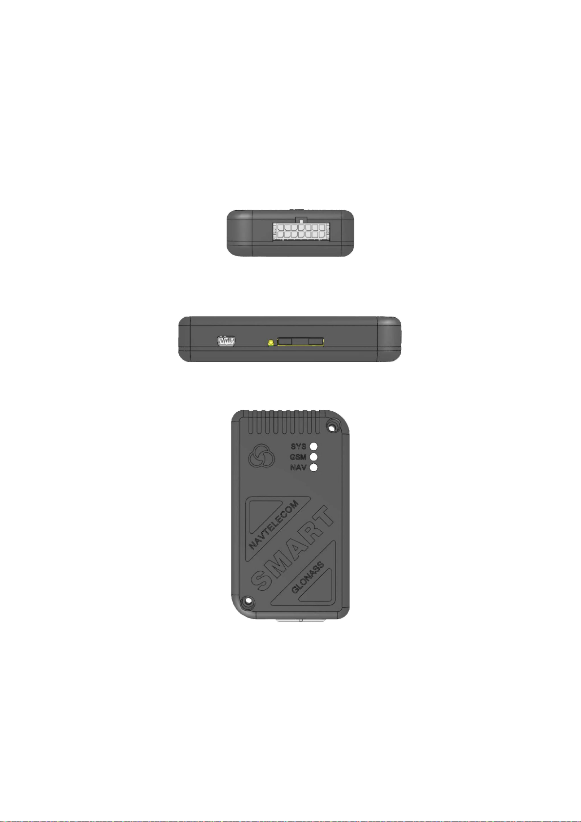
On the front part of the device unit (Figure 1) is located:
14-pin connector of Microfit-14 type for connection of power supply, digital and analog sensors and control lines.
On the side of the device unit (Figure 2) is located:
MiniUSB connector for connection with a computer;
SIM card holder slot with ejector (yellow button).
In the upper part of the device unit (Figure 3) there are three indicators:
system indicator (SYS)
modem operation indicator (GSM);
navigation receiver indicator (NAV).
Figure 1. Device unit (front view).
14-pin connector of Microfit-14
Figure 2. Device unit (side view).
MiniUSB connector and SIM card slot with ejector
Figure 3. Device unit (top view).
SYS, GSM, NAV indicators

1.6 Standard equipment set
Tab. 2
№
Name
Number of pieces
Version of complete set
A
B
1
Device unit
1
+
+
2
14-pin connector of Microfit-14 with two power wires
1
+
+
3
Cable set of 5 installation wires
1
+
+
4
Interface cable with MiniUSB connector
1
+
5
Passport
1
+
+
6
Package
1
+
Figure 4. 14-pin connector of Microfit-14
Figure 5. Interface cable with MiniUSB connector
Some cases may require connection of additional equipment not included in the standard equipment set, for example:
fuse and fuse holder;
fuel level sensor;
tachograph;
external LED;
temperature sensor;
TouchMemory contact key reader.
Figure 6. Fuse and fuse holder

Figure 7. Fuel level sensor
Figure 8. Tachograph
Figure 9. External LED
Figure 10. Temperature sensor
Figure 11. TouchMemory contact key reader
The manufacturer reserves the right to complete the devices with equipment whose set, appearance and
characteristics differ from those shown in the figures.

1.7. Device components
The device consists of the following elements (see Figure 12-15):
1) front cover;
2) fixing hole;
3) system LED indicator;
4) GSM LED indicator;
5) GLONASS / GPS LED indicator;
6) 14 pin connector;
7) MiniUSB connector;
8) SIM-card 1 ejector holder;
9) SIM-card holder 1 (external);
10) back cover;
11) fixing screw of the back cover - 4 pcs.
Figure 12
Figure 13
Table des matières
Autres manuels NAVTELECOM GPS


