NANOTEC BC72-50 Manuel utilisateur

Operating Instructions
Brake Chopper
For use with the following devices:
BC72-50
Operating Instructions Version: 1.2.0

Contents
1 Introduction.....................................................................................................3
1.1 Version information.....................................................................................................................................3
1.2 Copyright, marking and contact..................................................................................................................3
1.3 Intended use...............................................................................................................................................3
1.4 Warranty and disclaimer.............................................................................................................................4
1.5 Target group and qualification....................................................................................................................4
1.6 EU directives for product safety.................................................................................................................4
1.7 Used icons..................................................................................................................................................4
1.8 Emphasis in the text...................................................................................................................................5
2 Safety and warning notices..........................................................................6
3 Technical details and pin assignment.........................................................8
3.1 Environmental conditions............................................................................................................................8
3.2 Dimensioned drawings and installation options..........................................................................................8
3.3 Electrical properties and technical data......................................................................................................9
3.4 Pin assignment......................................................................................................................................... 10
3.4.1 X1 (PWR) −power supply............................................................................................................. 10
3.4.2 X2 (BRK) −external braking resistor (optional)............................................................................. 11
3.4.3 X3 (STS) −digital output (status output)....................................................................................... 12
3.5 LED signaling............................................................................................................................................12
4 Installation and commisioning................................................................... 14
4.1 Setting the switching threshold.................................................................................................................14
4.2 Connect the brake chopper......................................................................................................................15

1 Introduction
1 Introduction
During braking, electrical energy is fed back into the DC-link through self-induction of the motor. If not using
a power supply with regenerative-feedback capability, the brake power can cause the DC-link voltage
to increase which, if no additional measures are taken, is limited only by the internal consumption and
capacitances in the DC-link.
To prevent damage to the controller through overvoltage, it may – depending on the level of the braking
power – be necessary to dissipate excess energy in the form of heat. The brake chopper dissipates – if an
adjustable votlage value is exceeded – this excess energy via a resistor into heat.
1.1 Version information
Document
version Date Changes Hardware
version
1.0.0 05/2021 Edition W004
1.0.1 06/2021 Improvements in Setting the switching
threshold.W004
1.0.2 07/2021 Internal braking resistor overload leads to an
error. W004
1.1.0 10/2021 ■Overcurrent leads to an error.
■Added chapter Increasing the continuous
braking power
W004
1.2.0 12/2021 ■Mating connectors updated in chapter Pin
assignment
■Warning and safety messages updated
.
W004
1.2 Copyright, marking and contact
©2021 Nanotec Electronic GmbH & Co. KG. All rights reserved.
Nanotec Electronic GmbH & Co. KG
Kapellenstraße 6
85622 Feldkirchen
Germany
Phone: +49 89 900 686-0
Fax: +49 (89) 900 686-50
us.nanotec.com
1.3 Intended use
The brake chopper is used as a component of drive systems in various industrial applications.
Use the product as intended within the limits defined in the technical data (see Electrical properties and
technical data) and the approved Environmental conditions.
Under no circumstances may this Nanotec product be integrated as a safety component in a product or
system. All products containing a component manufactured by Nanotec must, upon delivery to the end user,
Version: 1.2.0 3

1 Introduction
be provided with corresponding warning notices and instructions for safe use and safe operation. All warning
notices provided by Nanotec must be passed on directly to the end user.
1.4 Warranty and disclaimer
Nanotec assumes no liability for damages and malfunctions resulting from installation errors, failure to
observe this manual or improper repairs. The selection and use of Nanotec products is the responsibility of
the plant engineer or end user. Nanotec accepts no responsibility for the integration of the product in the end
system.
Our general terms and conditions at www.nanotec.com apply.
Customers of Nanotec Electronic US Inc. please refer to us.nanotec.com.
NOTICE
Changes or modifications to the product are not permitted.
1.5 Target group and qualification
The product and this documentation are directed towards technically trained specialists staff such as:
■Development engineers
■Plant engineers
■Installers/service personnel
■Application engineers
Only specialists may install and commission the product. Specialist staff are persons who
■have appropriate training and experience in work with motors and their control,
■are familiar with and understand the content of this technical manual,
■know the applicable regulations.
1.6 EU directives for product safety
The following EU directives were observed:
■RoHS directive (2011/65/EU, 2015/863/EU)
■EMC directive (2014/30/EU)
1.7 Used icons
All notices are in the same format. The degree of the hazard is divided into the following classes.
WARNING
!The WARNING notice indicates a possibly dangerous situation.
Failure to observe the notice may result in severe or fatal injuries.
►Describes how you can avoid the danger.
CAUTION
!The CAUTION notice indicates a possibly dangerous situation.
Failure to observe the notice may result in moderately severe injuries.
►Describes how you can avoid the dangerous situation.
Version: 1.2.0 4

1 Introduction
NOTICE
Indicates a possible incorrect operation of the product.
Failure to observe the notice may result in damage to this or other products.
►Describes how you can avoid the incorrect operation.
TIP
Shows a tip for the application or task.
1.8 Emphasis in the text
The following conventions are used in the document:
Underlined text indicates cross references and hyperlinks:
■Use the product as intended within the limits defined by the technical data (see Electrical properties and
technical data)
■and under the approved Environmental conditions.
Text set in italics marks named objects:
■The NME2 is an external magnetic encoder for detecting the rotor position of motors.
Version: 1.2.0 5

2 Safety and warning notices
2 Safety and warning notices
WARNING
!
Risk of overheating or fire if the limits defined in the technical data (see Electrical
properties and technical data) are not observed and there is insufficient cooling!
►Do not use the product in potentially explosive areas (EX areas).
►During use, make certain that the cooling and environmental conditions are ensured.
►Ensure that good heat dissipation is favored by either installing the device in vertical position
or —if in a horizontal position— with the metal housing on top.
►Ensure that the permissible current is not exceeded when choosing an external braking
resistor.
►Monitor the status during commissioning and operation, via the LEDs and/or the status output.
CAUTION
!
Risk of injury from electric shock if the product is damaged!
If the product is damaged, voltage carrying parts can cause an electric shock which can possibly
lead to burns and injuries.
►Only change the wiring or touch the product in a de-energized state. After switching off, wait
at least three minutes until the voltage in the capacitors has dissipated.
CAUTION
!
Risk of injury in case of a short circuit!
A short circuit can damage the product and possibly lead to burns and injuries.
►If you notice a short circuit or the product signals an error via the LEDs and/or the status
output, immediately switch off the power supply. Commision the product again in a protected
environment and check the error message,
CAUTION
!
Risk of burning!
The product may become very hot during operation
►During use, make certain that the cooling and environmental conditions are ensured.
►Do not touch the product while in operation. After switching off, wait until all components have
cooled before you touch them.
CAUTION
!Risk of injury from sharp edges!
Due to production tolerances, sharp edges may form on the DIN rail clip and the mounting lugs
that could cause hand injuries.
►Do not touch the DIN rail clip or the mounting lugs to unpack or mount the product.
Version: 1.2.0 6

2 Safety and warning notices
CAUTION
!
EMC: Interference and risk of injury from electromagnetic alternating fields!
Current-carrying cables – particularly around supply cables – produce electromagnetic
alternating fields.
These can interfere with the product and other devices and lead to uncontrolled behavior and
injuries.
►Connect the product to earth over a short distance using the PE conductor.
►Perform a risk assessment for the entire machine/system to identify possible risks due to
electromagnetic interference and initiate suitable protection measures if necessary.
CAUTION
!
Risk of injury in case of electronics damaged through improper handling of ESD-sensitive
components!
The device contains components that are sensitive to electrostatic discharge. Improper handling
and lack of ESD protection measures can damage the device and lead to uncontrolled behavior
and injuries.
►Observe the basic principles of ESD protection when handling the device.
►If you notice an unexpected behavior, restart the device and check the correct LED signaling.
If an error is signaled, do not commission the device.
Version: 1.2.0 7

3 Technical details and pin assignment
3 Technical details and pin assignment
3.1 Environmental conditions
Environmental condition Value
Protection class according to EN/IEC 60529 IP30
Ambient temperature (operation) -10… +40°C
Ambient temperature (storage) -25… +85°C
Air humidity (non-condensing) 0 … 95%
Altitude of site above sea level 1500 m
3.2 Dimensioned drawings and installation options
All dimensions are in millimeters.
Version: 1.2.0 8

3 Technical details and pin assignment
You can secure the brake chopper with screws on a plane mounting surface using the lugs on the side or
install it with the delivered DIN rail clip in your switch cabinet.
CAUTION
!
Risk of overheating or fire if the limits defined in the technical data (see Electrical
properties and technical data) are not observed and there is insufficient cooling!
►During use, make certain that the cooling and environmental conditions are ensured.
►Ensure that heat dissipation is favored by either installing the device in vertical position or —if
in a horizontal position— with the metal housing on top.
3.3 Electrical properties and technical data
Property Description/value
Operating voltage 12 …75 V DC
Rated power @40°C 20 W (see table with assembly variants)
Power for max. 5 seconds 250 W
Max. permissible Power (for 1 second) 1 kW
Max. permissible current for internal and
external braking resistor (for 1 second) 40 A
Capacity of the integrated capacitors
(between power supply and ground) 400 µF
You can increase the continuous power up to 100 W by improving the heat dissipation and connecting an
external resistor at X2 (BRK). Nanotec recommends a 2.2 or 1.1 Ohm external power resistor parallel to the
internal 4.7 Ohm resistor.
Version: 1.2.0 9
3 Technical details and pin assignment
Assembly variant Continuous power @40°C
BC72-50 mounted on DIN-Rail 20 W
BC72-50 mounted on metal plate 30 W
BC72-50 with 2.2 Ohm external braking resistor,
mounted on metal plate 60 W
BC72-50 with 1.1 Ohm external braking resistor,
mounted on metal plate 100 W
NOTICE
Aside from the installation location and the heat transfer there, the exact temperature behavior is
also dependent on the convection in the application. For this reason, Nanotec recommends always
performing an endurance test in the actual environment for applications in which power and ambient
temperature pose a problem.
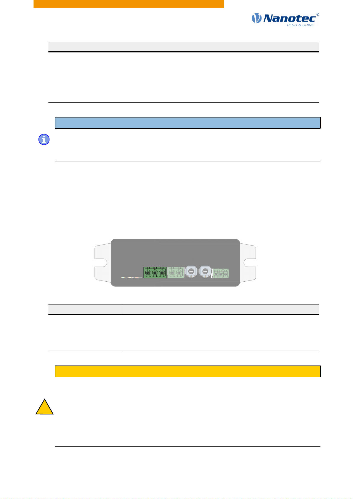
3.4 Pin assignment
3.4.1 X1 (PWR) −power supply
Type: DEGSON Electronics 2EDGRC-5.08-03P-14-00AH
Mating connector (included in scope of delivery): DEGSON Electronics 2EDGKD-5.08-03P-14-00AH or
equivalent
X1
1
Pin Function Note
1 PE Connection for the protective earth conductor
Connection for the supply voltage2 +Up12…75 V DC
3 GND Ground
CAUTION
!
EMC: Interference and risk of injury from electromagnetic alternating fields!
Current-carrying cables – particularly around supply cables – produce electromagnetic
alternating fields.
These can interfere with the product and other devices and lead to uncontrolled behavior and
injuries.
►Connect the product to earth over a short distance using the PE conductor.
►Perform a risk assessment for the entire machine/system to identify possible risks due to
electromagnetic interference and initiate suitable protection measures if necessary.
Version: 1.2.0 10
Table des matières
Manuels Sûr populaires d'autres marques


Honeywell
Honeywell 2077D - 1.21 Cubic Foot Anti-Theft Safe Manuel utilisateur

Hornady
Hornady SnapSafe Trunk Safe II Manuel utilisateur

SPORTS AFIELD
SPORTS AFIELD SA-HD5-BIO Manuel utilisateur

Honeywell
Honeywell 5912 Manuel utilisateur

Phoenix
Phoenix FS1280F Manuel utilisateur

Phoenix
Phoenix SS0992K Fiche d'information produit


