
Multilin PROTECT 4A-120 Manuel utilisateur

MOTOR PROTECTION RELAY
INSTRUCTION MANUAL

INSTRUCTION MANUAL
MOTOR PROTECTION RELAY
PATENTS U.S. 4,241,336 4,224,651
CANADA 1,130,383
COPYRIGHT 1982, 1986, 1988 MULTILIN
ALL RIGHTS RESERVED
215 Anderson Ave., PO Box 2700
Markham, Ontario, Canada L3P 4C7
Tel:(905) 294-6222 Fax:(905) 294-8512

TABLE OF CONTENTS
1. INTRODUCTION
1.1 Motor Protection Requirements................................................... 1
1.2 Protect 4A Features.....................................................................3
1.3 Typical Applications .....................................................................4
1.4 Order Code ..................................................................................5
1.5 Technical Specifications ..............................................................6
2. INSTALLATION
2.1 Physical Dimensions ...................................................................7
2.2 Mounting ......................................................................................9
2.3 External Wiring ..........................................................................10
2.4 Control Power ............................................................................ 11
2.5 Trip Contacts .............................................................................12
2.6 Thermistor Input ........................................................................12
2.7 Programmable Controller Output .............................................. 14
2.8 Tamper Proof Cover ..................................................................14
2.9 Field Options — Auto Reset ....................................................15
Mechanical Jam ............................................16
Ground Fault Indication Only ........................16
Single Phase Defeat .....................................17
Factory Service .............................................17
2.10 Environment ..............................................................................17
3. SETUP AND USE
3.1 Control and Indicators ............................................................... 19
3.2 Full Load Control .......................................................................20
3.3 StallTime Control ......................................................................23
3.4 Ground Fault (Earth Leakage) Level Control ............................ 24
3.5 Ground Fault (Earth Leakage)Time Delay Control...................25
3.6 Single Phase Detection .............................................................26
3.7 ThermistorTrip Detection ..........................................................27
3.8 Reset/Test Button ......................................................................28
3.9 MotorAmps Output....................................................................29
3.10 Fault Diagnosis ..........................................................................30
4. RELAYTESTING
4.1 CommissioningTests.................................................................31
4.2 Overloads ..................................................................................33
4.3 SinglePhasing...........................................................................34
4.4 Ground Fault/Earth Leakage .....................................................35
4.5 Thermistor .................................................................................37
4.6 4-20 mA Output ......................................................................... 38
4.7 Routine MaintenanceVerification .............................................. 39
4.8 ProblemTroubleshooting...........................................................40
5. THEORY OF OPERATION
5.1 Hardware ...................................................................................42
5.2 Firmware....................................................................................45

1
1. INTRODUCTION
1.1 MOTOR PROTECTION REQUIREMENTS
Three phase AC motors have become the workhorse of mod-
ern industry. Although motors are generally reliable devices,
many different causes ranging from abnormal conditions to op-
erator abuse can result in premature failure.Newer motors also
tend to be designed much closer to the normal operation limits
allowing less margin for abuse.
Sophisticated electronic relays are now normally used on large
high voltage motors to protect against a wide range of possible
fault conditions. High cost has precluded the use of these re-
lays on less expensive motors. In these applications, a simple
thermal overload is usually used.While inexpensive, these de-
vices only give limited protection under one type of fault condi-
tion — overloads.
The PROTECT 4A relay is designed to provide protection
against the four main causes of motor failure: overloads, single
phasing, ground faults (earth leakage) and overheating (ther-
mistor sensing).The Protect 4A relay is economical enough in
price that it can be used with low and medium voltage motors,
bridging the gap between expensive, sophisticated relays and
economical thermal overloads which are of limited effectiveness.
While no relay can prevent normal wear on the motor, the Pro-
tect 4A has been optimized to give maximum motor life without
unnecessary production shutdown from overprotection.Controls
are simple and self explanatory for ease of use.
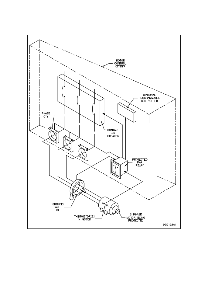
Current sensing is achieved through the use of separate phase
and ground fault CTs connected directly to the PROTECT 4A
relay.Three 5 amp or 1 amp secondary CTs are used to sense
motor phase currents. The three phase current wires pass
through the window of a 2000:1 CT for ground fault sensing.
2
FIGURE1-1 PROTECT4ATYPICAL SYSTEM CONNECTION
3
1.2 PROTECT 4A FEATURES
A microcomputer housed in a rugged, industrial package al-
lows the Protect 4A to provide accurate, economical protection
in a unit that will outlast the life of the motor. Since many new
factories are using programmable controllers as automation in-
creases, a 4-20mA output of motor current is also provided elimi-
nating the need for an additional transducer.This output gives
a direct reading of motor current.
Fault diagnosis after a trip is displayed on front panel indica-
tors. This will allow operators and electricians to rapidly isolate
and correct problems. It is possible to verify correct operation
of an installed Protect 4A relay to ensure that the motor protec-
tion is functioning properly.
One Protect 4A relay is required per motor. Phase and ground
fault currents are monitored through current transformers so that
motors of any line voltage can be protected.The relay is used
as a pilot device to cause a contactor or breaker to open under
fault conditions;that is, it does not carry the primary motor cur-
rent. Figure 1-1 shows how the Protect 4A is connected into a
system for complete motor protection.
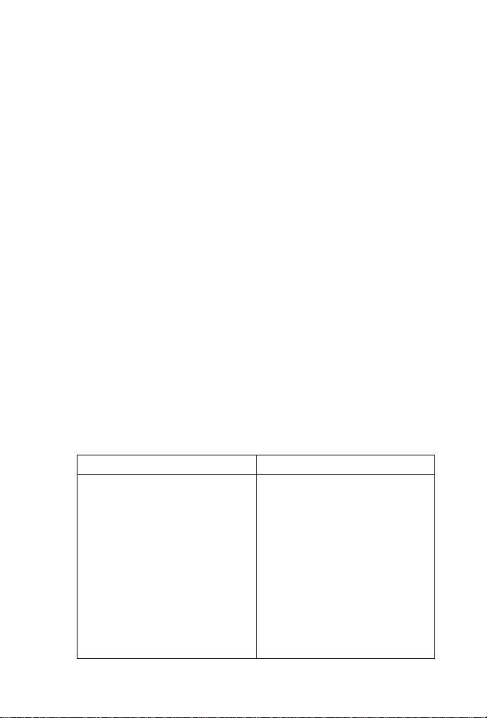
TABLE 1-1 PROTECT 4A FEATURES
FEATURES
•Fault Diagnosis
•4–20mA Output of Motor
Current
•Overload Status Indicator
•Economical
•Compact — Plug In
•Universal Models
Simplify Spares
PROTECTION
•Overloads
(8 Time Curves)
•Locked Rotor/Stall
•Mechanical Jam
•Multiple Starts
•Single Phasing
•Ground Fault/Earth
Leakage (Trip or indica-
tion only)
•Overheating (Thermistor
Sensing)

4
1.3 TYPICAL APPLICATIONS
Versatile features make the Protect 4A an ideal choice in a wide
range of motor applications.It should be considered for these
and other typical uses:
1) Basic protection on low and medium voltage motors. The
lowest horsepower selected for protection in an installa-
tion will depend on frequency of motor failure.
2)
Protection of motors and equipment from operator abuse
3) Personnel safety from shock hazard using sensitive ground
fault settings to detect winding shorts or leakage current
from moisture in mines.
4) Fault indication of ground fault without shutdown to warn
that corrective maintenance is required.
5) Mechanical protection of gears, pumps, fans, saw mills, cut-
ters and compressors against mechanical jam.
6) Simplified spare parts stocking using one universal model
to cover all motor sizes and settings.
7) Output of motor current suitable for programmable controller
interface (4–20mA).
The motor phase currents are sensed by 3 conventional 1 amp
or 5 amp secondary current transformers (CTs). If ground fault
sensing is required then a separate zero sequence ground fault
CT, through which all 3 phase conductors pass, is required.This
CT is available in 2 sizes:HGF-3 (3½" diameter window) or HGF-
5 (5½" diameter window).
Note: Ground fault sensing only works on systems that are solid
or resistance grounded. Ungrounded systems require an artifi-
cial ground, through the use of a zigzig transformer, for ground
fault sensing to work.
5
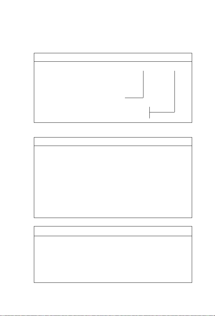
PHASE SENSING CURRENT TRANSFORMERS
Any standard 5 amp secondary 5 VA or greater CT can be
used. 3 phase CTs per PROTECT 4A are required. 1 amp
CT operation available on special order.
PART NO. DESCRIPTION
CT-100:5 100:5
CT-150:5 150:5
CT-200:5 200:5
CT-250:5 250:5
CT-300:5 300:5
CT-500:5 500:5
CT-1000:5 1000:5
1.4 ORDER CODE
TABLE 1-2 RELAY ORDER CODE
RELAY PROTECT 4A — 120
PART NO. DESCRIPTION
PROTECT 4A Standard relay
— 120 120 VAC control voltage
— 240 240 VAC control voltage
GROUND FAULT CURRENT TRANSFORMERS
1 required for ground fault sensing:
PART NO. DESCRIPTION
HGF3 3½" Window 2000:1
HGF5 5½" Window 2000:1

6
1.5 TECHNICAL SPECIFICATIONS
TABLE 1-3 TECHNICAL SPECIFICATIONS
FULL LOAD CURRENT
50-100% PHASE CT RATING
INPUT: 0-8 TIMES MAXIMUM RANGE
CURRENT
FREQUENCY: 48-62 Hz, 3 PHASE SINUSOID
MAXIMUM INPUT: 8 TIMES FULL LOAD 25 SECONDS
12 TIMES FULL LOAD 2 SECONDS
FULL LOAD CONTROL — AMPS
RANGE: 50-100% PHASE CT RATING
CALIBRATED VALUE:3 PHASE SINEWAVE-RMS
EQUIVALENT
PICKUPACCURACY: ±5% FULLSCALE
OVERLOAD TIMES: ±10%CURVEVALUE
MECHANICAL JAM: ACTIVATED AT 3 TIMES FULL LOAD
SETTING IF ENABLED.
NOMINAL DELAY — 1 SECOND
SINGLE PHASE
ACTIVATION: SEVERE UNBALANCE/SINGLE
PHASE DEFEATED IF MOTOR
AVERAGE CURRENT < 40% FULL
LOAD SETTING
TRIP DELAY: 5 SECONDS ±2 SECONDS
THERMISTOR INPUT
HOT TRIP
RESISTANCE: 2800-3300 OHMS
COLD RESET
RESISTANCE: 250 OHMS MAX
TRIP DELAY: 3SECONDS ±1 SECOND
THERMISTOR MEMORY MODEL
ACTIVE: MOTOR RUNNING/STOPPED WITH
CONTROL POWER
CLEAR: POWER ON OR RESET AFTER TRIP
COOL RATE: 5 MINUTES TO CLEAR MEMORY
@10 SEC STALL SETTING
RESET: NOLOCKOUT ON TRIP
GROUND FAULT/EARTH LEAKAGE
TRIP LEVEL: 1-10A ±15% PRIMARY CURRENT
FULL SCALE
(0.5A MAX WITH CONTROL FULLY
ANTI-CLOCKWISE)
TRIP DELAY: TIMES AT < 25% PICKUP
THRESHOLD
30ms 7-30ms TYPICAL 30ms MAX
50,100ms: ±15ms
200, 300, 500, 750,
100ms:±15%
MOTOR AMPS OUTPUT
OUTPUT CURRENCY: 4 mA = 0 AMPS
20 mA = PHASE CT RATING
ACCURACY: LINEAR ±5% FULL SCALE
MAXIMUMLOAD
RESISTANCE: 350 OHMS
SATURATION
OUTPUT: 30mAMAX
OUTPUT CONTACTS
TYPE: SINGLE FORM C NO/NC
SILVER CADMIUM OXIDE
RATINGS: STANDARD PILOT DUTY
120/240 VAC 10 AMPS
@ 80% P.F.
360VA
28 VDC 10 AMPS
CONTROL POWER
120VAC INPUT RANGE: 85-140 VAC
240VAC INPUT RANGE: 170-280 VAC
FREQUENCY: 48-62 Hz
POWER: 5VA
PHYSICAL SHIPSHIP
SHIPSHIP
SHIP CARCAR
CARCAR
CARTONTON
TONTON
TON
PRODUCTPRODUCT
PRODUCTPRODUCT
PRODUCT WEIGHTWEIGHT
WEIGHTWEIGHT
WEIGHT DIMENSIONSDIMENSIONS
DIMENSIONSDIMENSIONS
DIMENSIONS
PROTECT 4A 4 lbs 5¼" × 5¼" × 7½"
8.8 kg 133mm×133mm ×191mm
HGF3 2.2 lbs 2½" × 6½" × 6½"
1 kg 64mm× 165mm× 165mm
HGF5 3.8 lbs 3"× 8" ×9"
1.5 kg 76mm× 204mm× 228mm
ENVIRONMENT
TEMPERATURE RANGE
–10°C — +60°C
CERTIFICATION: CSA
7
2. INSTALLATION
2.1 PHYSICAL DIMENSIONS
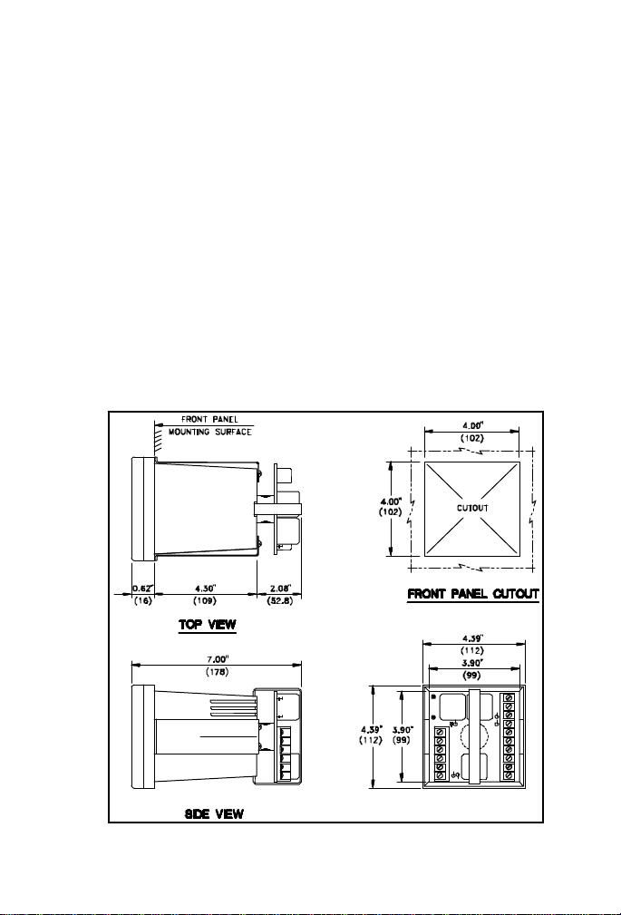
Dimensions of the Protect 4A relay and mounting components
are shown in fig.2-1.Both the clear cover and the terminal board
are detachable from the relay.The case is made of rugged plastic
with a clear cover for viewing indicators and control settings.
Phase CTs with 1 amp or 5 amp secondaries should be used.
These can be standard CTs which are user supplied. Dimen-
sions for CTs available from Multilin are shown in figure 2.2. If
zero sequence ground fault detection is required, the appropri-
ate ground fault CT shown in figure 2-3 must be installed.
FIGURE 2-1 RELAY DIMENSIONS
REAR VIEW
Ce manuel convient aux modèles suivants
1
Table des matières
Autres manuels Multilin Relais


