MSG MS021 Manuel utilisateur

MS021
UNIQUENESS
QUALIT Y SERVICE
WARRANTY TRAINING
INNOVATION
2020.03.20
USER MANUAL
TESTER FOR DIODES & RECTIFIERS
INSTRUKCJA OBSŁUGI
STANOWISKO DIAGNOSTYCZNE DO
TESTOWANIA GENERATORÓW SAMOCHODOWYCH
РУКОВОДСТВО ПО ЭКСПЛУАТАЦИИ
ТЕСТЕР ДЛЯ ПРОВЕРКИ ДИОДНЫХ
МОСТОВ


1
User Manual - MS021 Tester
English
INTRODUCTION...........................................................................................................................................................2
1. PURPOSE ................................................................................................................................................................. 2
2. TECHNICAL CHARACTERISTICS...........................................................................................................................3
3. EQUIPMENT PACKAGE...........................................................................................................................................4
4. DESCRIPTION OF THE DEVICE.............................................................................................................................4
5.
OPERATION
............................................................................................................................................................... 5
5.1 Safety regulations..........................................................................................................................................6
5.2 Rectier testing..............................................................................................................................................6
5.3 Tester setup ....................................................................................................................................................8
6. TESTER MAINTENANCE.........................................................................................................................................8
6.1 Cleaning and Care..........................................................................................................................................9
7. MAJOR FAULTS AND TROUBLESHOOTING....................................................................................................... 9
8. EQUIPMENT DISPOSAL ......................................................................................................................................10
CONTENTS

Thank you for purchasing the MSG Equipment product.
Tester for diodes and rectiers is manufactured from quality components and materials.
This manual contains information about the purpose, conguration, design, operation, technical
characteristics and operating rules of MSG MS021 tester.
The manufacturer reserves the right to change the design and software without prior notice to
users.
Read carefully this manual before putting MS021 (hereinafter referred to as the “Device”) into
operation, get special training at the equipment manufacturing facility if necessary.
MS021 has been engineered to satisfy the demand of big service stations and alternator repair
shops for the device which would allow quick and accurate rectier health checks. Testing
rectierswiththe useof multimeter has always beenthe most common practice.This method has a
signicant drawback -it doesn't help to identify the diode type and nd the faulty one. The test
current of a standard multimeter is about 0.002A, which is too low compared to the diode
operating currents.The test currentof MS021 is 0.9A which allows accurate diagnosingofa diode.
2
MS021 is designed to test the performance and structural integrity of automotive alternator
rectiers as well as of diodes separately.
The device detects:
-type of a diode (standard or avalanche);
-degradation of a diode (excessive forward voltage drop);
-avalanche diode reverse-breakdown voltage;
-diode breakdown;
-diode open-circuit failure;
-poor contact between the diode and the conductive busbars.
INTRODUCTION
1. PURPOSE
User Manual - MS021 Tester
English

3
2. TECHNICAL CHARACTERISTICS
3. CONTROL DEVICES
Dimensions (L*W*H), mm 219×214×80
Weight, kg 2
Supply voltage, V 230
Supply frequency, Hz 50
Supply type Single-phase
Consuming power, W No more than 40
Current load of diode test, A 0,9
The voltage on the open contact probes of the
device, V 30
Operating temperature, C˚ From +10 to +40
Storage temperature, C˚ From 0 to +50
User Manual - MS021 Tester
English

The MS021 package includes:
-MSG MS021 tester – 1 pc.;
-power cable – 1 pc.;
-diode fuse – (type: 5*20mm, current: 0.5A) – 1pc.;
-cable with a probe – 1 pc.,
-cable with a clamp – 1 pc.,
-User Manual – 1 pc.
Inspect MS021 tester. If any damage is detected, please contact the manufacturer or sales
representative before launching the equipment.
4
3. EQUIPMENT PACKAGE
4. TESTER DESCRIPTION
WARNING! In case of obvious damage, the operation of the device is forbidden.
The device is supplied with a touch screen (“1” - Fig.1) which displays the tested parameters; the
color indication of the screen signals the technical condition of the tested diode. The tester has
two connection terminals (“2” - Fig.1) for diagnostic cables (Fig.2). Any connection conguration
of cables is allowable. The encoder knob (“3” – Fig.1) is used for ne adjustment of the device for
specic tasks. Button “4” turns the device on. Diode fuse and power connectors are located at the
rear of the device.
Fig.1 MS021 tester. General view:
1 – Touch screen; 2 – Connection terminals for diagnostic cables;
3 – Encoder button; 4 – “ON” button.
123 4
User Manual - MS021 Tester
English

5
Fig.2. Diagnostic cables
Fig.3. MS021 tester. Back view:
1 – Diode fuse; 2 – Power connector.
2
1
5. OPERATION OF THE DEVICE
1.Use the device as intended.
2.The tester is intended for indoor use. When used outdoors, external conditions and technical
characteristics of the device set out in item 2 of this manual, should be taken into consideration.
3.To avoid failure or damage to the tester, do not make any changes to the electrical diagram of
the device on your own. In case of failure, please contact the manufacturer or sales
representative.
4.Do not leave the device with closed probes for more than 2 minutes.
5.Working with a measuring probe, keep your ngers on the plastic part of it. Touching the metal
part of the measuring probe may cause measurement errors.
User Manual - MS021 Tester
English
6
6.The device is equipped with a system for diagnostics of the probes condition. If any fault is
detected, the "PROBE PROBLEM" message will appear on the screen. The "DIODE BREAKDOWN"
message that appears when the probes are open, signals the probe failure. Check the
connection of the probes and ifthe problem persists, contact the customer service.
1.0nly the personnel that has received special training in safety operation and been authorized
to work with the test benches (devices) of certain types is allowed to use the device.
2.Make sure that measuring clamps do not have insulation damage or bare metal spots. Check the
clamps for any breaks. In case of obvious damage, replace them with the new ones before
launching the device.
Diagnostics of a rectier should be performed as follows:
1.Turn the tester on. Connect the clamp to the rectier housing. The following message will appear
on the screen: “CONNECT PROBE TO DIODE”.
2.Touch the contact spot of the tested diode with a probe. The following information will be
displayed:
“Vf” – diode voltage drop (in volts);
"Vr" - stabilizing voltage (in volts). If there are stabilitrons (avalanche diodes) in the rectier
structure, the "AVALANCHE" message will appear.
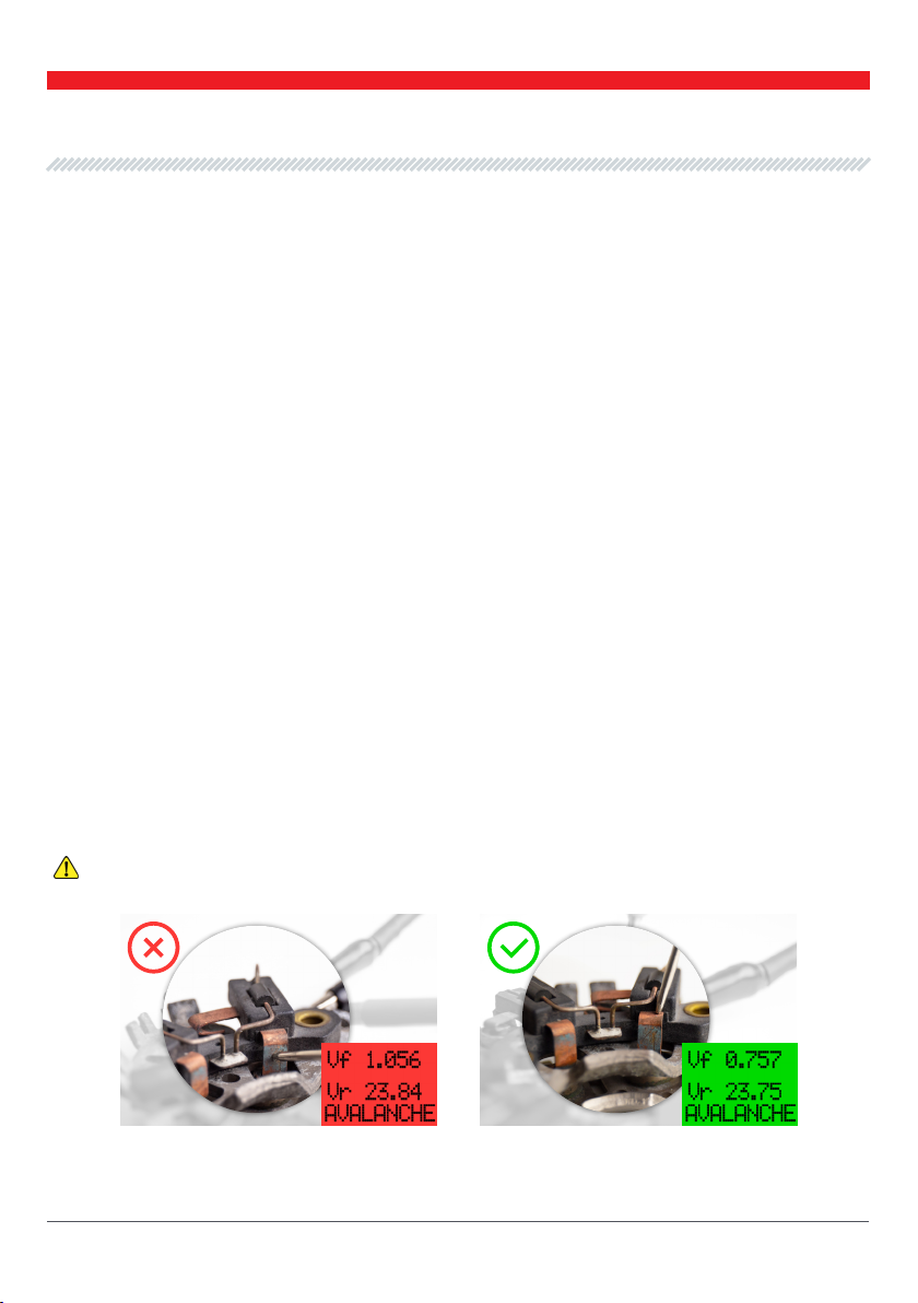
WARNING! Different contaminants and dirt on the tested contacts may lead to measurement
errors.
5.1. Safety regulations
5.2. Rectier testing
Б
Fig.4. Taking measurements.
А) – incorrect; Б) – correct
А
User Manual - MS021 Tester
English

7
2.1. If the diode is faultless, the screen will display “Vf” and “Vr”
values. The screen color will be green.
2.2. If the "Vf” value is higher than normal, the screen color will be
yellow.
2.3. If the diode is faulty, the screen color will be red.
The operability of the rectier should be decided on the basis of the “Vf” readings and type
(model) of the diode (stabilitron). The “Vf” absolute value is not always a key parameter when
checking the rectier. It is important to pay attention to the spread between the “Vf” values of
different diodes of the same rectier. For example, for a rectier that can carry 50 A, “Vf” = 0.850
V is quite typical. The rectier can be considered faultless If the spread between “Vf” values of
the diodes doesn’t exceed ± 0.020 V. For the 120A rectier, "Vf" = 0.850V is already a critical value.
The diode with such a "Vf" value shall be considered faulty.
2.4. In case of a short or open circuit failure, the screen color will be red and either the “SHORT
CIRCUIT’ or ‘DIODE BREAKDOWN’ message will be displayed correspondingly.
User Manual - MS021 Tester
English

8
The device assesses the diode performance on the basis of the forward voltage drop value (“Vf”)
and is specially calibrated to make it usable for any operator who doesn’t have sufcient
knowledge of the diode parameters and characteristics. Threshold values can be changed at the
user’s option.
Enter the “Settings” menu as follows:
1)Turn the device off.
2)Press and hold down the encoder button (“3” – Fig.1)
3)Turn the device on. A setup mode will be activated.
4)Threshold values for either a faultless diode (green color of the screen) or a faulty one (red
color of the screen) can be changed in this mode.
5)The selected threshold value can be changed by turning the encoder button clockwise or
counterclockwise.
6)To save the selected settings, press and hold down the encoder button until the device enters
the operating mode and the “CONNECT PROBE TO DIODE” message appears on the screen.
7)Turn the tester off to exit the setup menu. The settings won’t be saved.
5.3. Tester setup
Fig.5. Color threshold setting menu.
The test bench is designed for a long-continued full-time operation. However, to ensure uptime
of the test bench, it is necessary to provide regular technical inspection of the device and below
described routine maintenance as recommended:
The following main points should be checked in the course of a daily inspection:
•Whether the environment is permissible for the tester operation (temperature, humidity, air
pollution, vibration, etc.).
6. TESTER MAINTENANCE
User Manual - MS021 Tester
English
Table des matières
Langues :
Autres manuels MSG Équipement de test


Manuels Équipement de test populaires d'autres marques

SMART
SMART KANAAD SBT XTREME 3G Series Manuel utilisateur

Agilent Technologies
Agilent Technologies BERT Serial Manuel utilisateur

Agilent Technologies
Agilent Technologies N3280A Manuel utilisateur

Vernier
Vernier Go Direct Voltage Manuel utilisateur

Lifeloc
Lifeloc R.A.D.A.R. Manuel utilisateur

Fluke
Fluke T5-600 Instructions d'utilisation et d'installation


