Motic MLC-150C Manuel utilisateur

ENS LYON
tlotîc
Cold Light Power Supply
MLC-1 50C
Instruction Manual
WWW.MOTIC.COM
MOTIC INCORPORATION LTD.
C€ @ ,t- Listed Product E2so223
f;!;.lffiiir1l9.1:

We are constantly endeavoring to improve our instruments and to adapt them to the
requirements of modem research techniques and testing methods. This involves modification
to the mechanical structure and optical design of our instruments.
Therefore, all descriptions and illustrations in this instruction manual, including all
specifications are subject to change without notice.
To ensure proper use, please read this manual carefully before using the MLC-150 cold light
source.
To meet the demands of both international and domestic markets, Motic has developed the new
MLC- l50C cold light source. Besides a switching power supply that ensures a regulated voltage
for the lifetime of the halogen bulb, many other safety precautions have been taken to provide a
safe and reliable cold light source. In addition, an infrared filter and filter assembly have been
incorporated to minimize halogen light heat output in order to achieve cold light illumination and
meet the objectives of many kinds of color temperature light rays.
The MLC-150C can be applied extensively in various fields that require bright light illumination
including' microscopy, medicine, education, and many other areas of scientific research. With a
sturdy construction, practical and aesthetic design, minimal working noise and user friendly
controls' it is a welcome addition to any laboratory. A large selection of additional fiber liehts are
also available to choose from.

Contents
1. Specifïcations
2. Fiber optic lights
3. Usage
4. Installing the filter
5. Changing the bulb
6. Color temperature display
7. Maintenance and Care
8. Accessories
4
5
7
l0
11
L2
13
I4

1. Specifications
1. Input rating
2. Output rating
3. lnternal i lluminator
4. Illuminarion outpur
5. Color temperature output
6. Environment
T.Breaking capacity
S.Intemal fuse
9. Average problem-free usage
10. Total area
11. Weight
AC115V/AC230V +15% 50/60H2 2OOW
DC3V-DC2|Y + t0% (halogen lamp working voltage)
7A (MAX)
2Mf50W EKE Halogen lamp; Working life 200H
> 120000LX
A. With no filter: 2500K-3200K
B. With filter: 5000K (Max)
A. Active temperature : 0C^45C
B. Storage temperature: -10"C^60C
C. Active and storage humidity:
At 31 degrees, corresponding humidity at80Vo,
At 40 degrees, decrease conesponding humidity to 5OVo.
D. Elevation: 2000m max
E. Installation Category: II
F. Pollution rating:2
G. Active environment quality: conductive dust and corrosive
gas free.
H. Indoor use only
1750VAC / 5MA/one minure without breaking
T5AL250V low breaking capacity glass tube fuse (with delay)
MTBF>lOOOOH
220 (w) X 193 (L) X 112 (H) mm
3Ks

2. Fiber optic lights
Note: Customizations can be made for user-specific requirements.
Serial No. Length lYpe Diameter Output plug Microscope
sP990072 1.5M Flexible ù7 Straight
K-model
stereomicroscope,
verlical
illuminator
sP9900734 2M Flexible ô5 Straight Industrial
microscopes
sP9900738 2M Flexible ôs Elbowed Industrial
microscopes
sP990074 1M Flexible ô5 Inner diameter
61MM Ring lamp
Stereomicroscopes
K and
SMZ168 models
sP990075 0.5M Hard-tube
(single) ô8 Straight
Gemological
microscopes
GM168 and
GM143 models
sP990076 0.5M Hard-tube
(twin) ô s.6 Straight K-model
stereomicroscope
Table 1

Flexible fiber optic light -
sP990072
Industrial microscope fiber optic light -
sP990078
Hard-tube single fiber optic lighr -
sP990075
Industrial microscope fiber optic light -
sP99007A
Ring light -
sP990074
'/
g
'. t-
t;,
Hard-tube twin fiber onric liphr -
sP990076

3. Usage
1. Confirrn your local power supply rating and then at the back of the unit adjust the voltage
conversion switch accordingly (115V or 230V).
1. Controller cable input
2. Light control mode switch
3. Voltage conversion switch
4. AC input
Diagram 1
2. Users are able to choose the tight intensity control method as required. Shorl-range control
method: Switch the 'Light control mode switch'to 'LOCAL' (see diagram 1). Place the unit
on your desk and use the light intensity adjustment knob on the front panel of the unit to
adjust the light intensity. Remote control method: Switch the 'Light control mode switch' to
'REMOTE' (see diagram 1). Place the unit anywhere within 1.5 meters (as the cable allows)
of your person, plug the remote control cable into the main unit using the DB9 plug and begin
to adjust light intensity using the remote control.
1. AC power switch
2.Light intensity adjustment dial
3. Lamp housing screws

i:||ee
3. Select the appropriate fiber optic light from table 1 as required. Next, insert the light into the
socket as shown in diagram 3 and tighten the holding screws on the lamp housing.
',t* '* | -:
x{
1. Fiber optic light socket
2. Fiber optic light plug
Diagram 3
Plug the power cable into the AC input socket on the back panel of the unit (see diagram 1).
From the front panel, turn the power on, at which point the LED indicator light will illuminate
indicating the power has been connected and the cold light source has begun working. Adjust
the light intensity dial making sure the outpllt light changes from bright to dark or vice versa.
Install the light-output end of the fiber optic light in the appropriate location on your
microscope or any other location that requires cold light illumination and begin use.
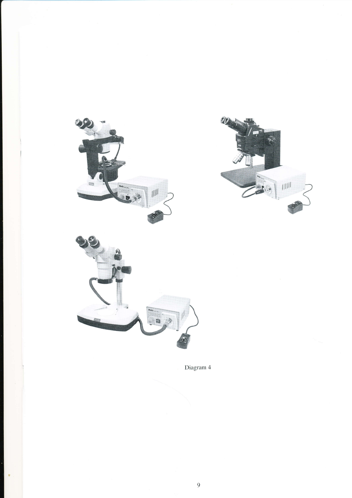
Once the cold light source has been properly assembled and tested it can be placed alongside
(effective within a 1.5 meter range) and used with your microscope or any other device
requiring cold light. Be sure the front panel of the control box is free from obstruction as this
will ensure the user is able to conveniently adjust the light intensity and/or switch fiber lights
as necessary. (see diagram 4 for suggested setup)
ôx
4.
5.
%:
Diagram 4
Table des matières


