Morrison Bros. co. 918AC Series Manuel

1
Morrison Bros. Co. ‑ Dubuque, IA ‑ 800‑553‑4840
918AC‑0142 PP
!
!
rev.10-20-2021
The 918AC Series is designed to provide a visible and audible alarm. It is an A.C. powered device intended
to be located in an ordinary location. The 918AC Series System Interface is congurable for one to four
Intrinsically Safe, normally open or normally closed, dry contact inputs and from zero to four form C (SPDT),
dry contact outputs. The outputs may be congured as normally disengaged or normally engaged (fail-safe).
Two possible applications are use as an overll alarm or as an interstitial alarm.
Failure to follow any or all of the warnings and instructions in this document could result in a hazardous
liquid spill, which could result in property damage, environmental contamination, re, explosion, serious
injury or death.
Le fait de ne pas se conformer à l’un ou l’autre des avertissements ou à l’une ou l’autre des directives
apparaissant dans ce document pourrait donner lieu à des déversements de liquides dangereux, lesquels
pourraient engendrer des dommages matériels, des risques de contamination environnementale,
d’incendie ou d’explosion, des blessures graves ou la mort.
Contents
Specications.....................................................................................................................................2
Installation and Testing......................................................................................................................3
Mounting ......................................................................................................................................4
Steps to Wire and Congure the System Interface............................................................................5
Input Module(s) ............................................................................................................................5
Facilities Section of the System Interface ....................................................................................7
Output Module(s) (if so equipped) ............................................................................................... 8
Completion ...................................................................................................................................10
Steps to Congure the 918AC Series System Interface Motherboard ..............................................11
Auto-Silence .................................................................................................................................11
Audible Alarm ..............................................................................................................................12
‘Heartbeat’ Function ......................................................................................................................13
Steps to Test the 918AC Series System Interface.............................................................................. 14
Operation ...........................................................................................................................................16
Use as an Overll Alarm ..............................................................................................................16
Use as in Interstitial Alarm ...........................................................................................................16
Maintenance ..................................................................................................................................... 17
Monthly ........................................................................................................................................17
Yearly........................................................................................................................................... 18
DIP Switch Conguration Tables ......................................................................................................19
Input Module ................................................................................................................................19
Output Module..............................................................................................................................19
Motherboard .................................................................................................................................19
Replacement Parts .............................................................................................................................21
918AC System Interface Control Drawing B-7767-14.....................................................................22
918AC Series System Interface
Installation, Operation, and Maintenance Instructions

2
Morrison Bros. Co. ‑ Dubuque, IA ‑ 800‑553‑4840
918AC‑0142 PP
rev.10-20-2021
Specications
Description
The 918AC Series System Interface is intended to be located in an Ordinary Location. Its inputs are
intrinsically safe for use with Class I, Division 1 Group D. T4 Hazardous location with either normally open or
normally closed dry contacts.
WARNING: This is an intrinsically safe device and must be wired in accordance with National Electrical Code
Article 500. This device and its wiring may not share any junction box, conduit, or raceway with any other type
circuit or wiring. Do not perform live maintenance. Do not substitute components with anything other than
Morrison Bros. Co. components. Care must be taken to avoid an ignition hazard from impact or friction with the
enclosure.
AVERTISSEMENT: Cet appareil intrinsèquement sécuritaire doit être branché conformément à l’article
500 du code électrique national. Il se peut que ce dispositif et son câblage ne partagent pas de boîte de
connexion, de conduit ou de canalisation avec un autre type de circuit ou de câblage. Ne menez pas de travaux
de maintenance sous tension. Ne remplacez les composantes que par des composantes de Morrison Bros. Co.
Assurez-vous d’éviter le risque d’inammation pouvant découler d’un impact ou de friction avec l’enceinte.
Entity Parameters for Channel Inputs (Terminal P1 on each Dry Contact Input Module)
VOC = 4.935 VDC ISC = 99.697 mA Ca = 0.37 μF La = 1.43 μH PO = 0.123 W
Output Module Contact Rating
240 VAC Maximum
5 Amps Maximum
System Interface Input Power
Nominal Input Voltage: 120/240VAC
Maximum Current Draw: 0.0325A
Maximum Power Consumption: 1.77W
Line Frequency: 50/60Hz
Power Supply Protection Fuse Rating: 1.0A FA 5x20mm
Operating Temperature
-40ºF to 140ºF (-40ºC to 60ºC) to 100% humidity
Enclosure Rating
NEMA 4X
Maximum Wiring Distance
Maximum wiring distance between Alarm and input device is 5000 ft.

3
Morrison Bros. Co. ‑ Dubuque, IA ‑ 800‑553‑4840
918AC‑0142 PP
rev.10-20-2021
!
!
Installation and Testing
WARNINGS
• Fire Hazard – Death or serious injury could result from spilled liquids.
• You must be trained to install or maintain this alarm. Stop now if you have not been trained.
• Any modication of this unit beyond what is outlined in this instruction will void product warranty.
• For your safety, it is important to follow local, state, federal and/or OSHA rules that apply to working inside,
above, or around the storage tank and piping area. Use all personal protective equipment required for working
in the specic environment.
• This device is intended to be used as an auxiliary warning to the operator of an abnormal condition of
the system, such as a possible overll situation and should not be the only system in place to prevent an
unwanted condition, such as preventing a tank from overlling. It is the sole responsibility of the operator to
continuously prevent any spillage regardless of the situation.
• Tanks could be under pressure. Vapors could be expelled from tank vents, piping, valves or ttings while
performing maintenance. Vapors could catch re or cause an explosion. Avoid sparks, open ame, or hot tools
when working on tank system.
• Use a dampened cloth when cleaning the alarm enclosure to prevent static buildup and discharge.
• In the event of malfunction, contact Morrison Bros. Customer Service.
AVERTISSEMENTS
• Risque d’incendie – Un déversement de liquide pourrait entraîner des blessures graves ou la mort.
• Vous devez avoir reçu une formation pour installer cette alarme ou en assurer la maintenance. Arrêtez-vous
immédiatement si vous n’avez reçu aucune formation à cet eet.
• Toutes les modications apportées à cette unité autres que celles indiquées dans ces directives engendreront
l’annulation de la garantie du produit.
• Pour assurer votre sécurité, il est important de vous conformer à la réglementation locale, d’État, fédérale
ou OSHA régissant les travaux à l’intérieur, au-dessus ou autour du réservoir de stockage et de la zone de
canalisation. Utilisez tout l’équipement de protection individuelle exigé pour travailler dans l’environnement
spécique.
• Cet appareil est destiné à être utilisé comme mécanisme avertissant l’opérateur d’un état anormal du système
tel une situation de remplissage excessif et ne devrait pas être le seul système en place pour empêcher un état
indésirable, par exemple, un réservoir qui se remplit trop. L’opérateur a l’entière responsabilité de s’assurer
continuellement de prévenir tout déversement, quelle que soit la situation.
• Les réservoirs pourraient être sous pression. Des vapeurs pourraient être expulsées des conduits d’aération,
des canalisations, des soupapes ou des raccords du réservoir durant la maintenance. Les vapeurs pourraient
s’enammer ou engendrer une explosion. Évitez les étincelles, les ammes nues ou les outils chauds lors de
travaux menés dans le système du réservoir.
• Utilisez un linge humide pour nettoyer l’enceinte de l’alarme an de prévenir l’accumulation d’électricité
statique et les décharges.
• En cas de défaillance, communiquez avec le service à la clientèle de Morrison Bros.
Note: As dened in Article 501 – Class 1 Locations of NFPA 70, this apparatus and its connected wiring are
intrinsically safe. Under normal conditions this apparatus and its wiring cannot release sucient energy to
ignite a specic ignitable atmospheric mixture by opening, shorting, or grounding.

4
Morrison Bros. Co. ‑ Dubuque, IA ‑ 800‑553‑4840
918AC‑0142 PP
rev.10-20-2021
WARNING:
Interconnect wiring between the sensor(s) and the System Interface unit must be kept totally isolated and
separate from any other wiring. This wiring must not share any junction box, conduit, raceway, or xtures with
circuits other than those dened by NEC as being intrinsically safe for all Class 1 locations.
These inputs are ground referenced and only require “basic insulation.”
AVERTISSEMENT:
Le câblage d’interconnexion entre la jauge et l’unité d’alarme doit être complètement isolé et distinct du reste
du câblage. Le câblage ne doit partager aucune boîte de connexion, aucun conduit, aucune canalisation, ni
aucun accessoire avec des circuits autres que ceux dénis par NEC comme étant intrinsèquement sécuritaires
pour tous les emplacements de classe 1.
Ces entrées sont mises à la terre et ne requièrent qu’une « isolation de base ».
Location:
The System Interface enclosure is only approved for operation outside of all hazardous locations as dened by
the National Electrical Code or NFPA 70.
Mounting
To maintain the enclosure’s NEMA 4X rating
• Three openings have been provided in the bottom of the NEMA 4X enclosure for
connection and wiring. Only use Thomas & Betts Cat. No. H050GR-TB or H050-TB or
equivalent ½” hubs in these openings.
• Mounting tabs have been provided with the product to mount the enclosure; do not make
additional holes in this enclosure.
• Ensure that both cover latches are latched at all times.
Failure to follow these instructions voids any assurance that the enclosure is NEMA 4X.
!

5
Morrison Bros. Co. ‑ Dubuque, IA ‑ 800‑553‑4840
918AC‑0142 PP
rev.10-20-2021
Steps to Wire and Congure the System Interface
Imput Module(s)
1. Preparation
a. Open the front cover of the System Interface by releasing the two cover latches and swinging the
cover open.
b. Remove and retain the two screws with their at washers. Remove the metal cover of the
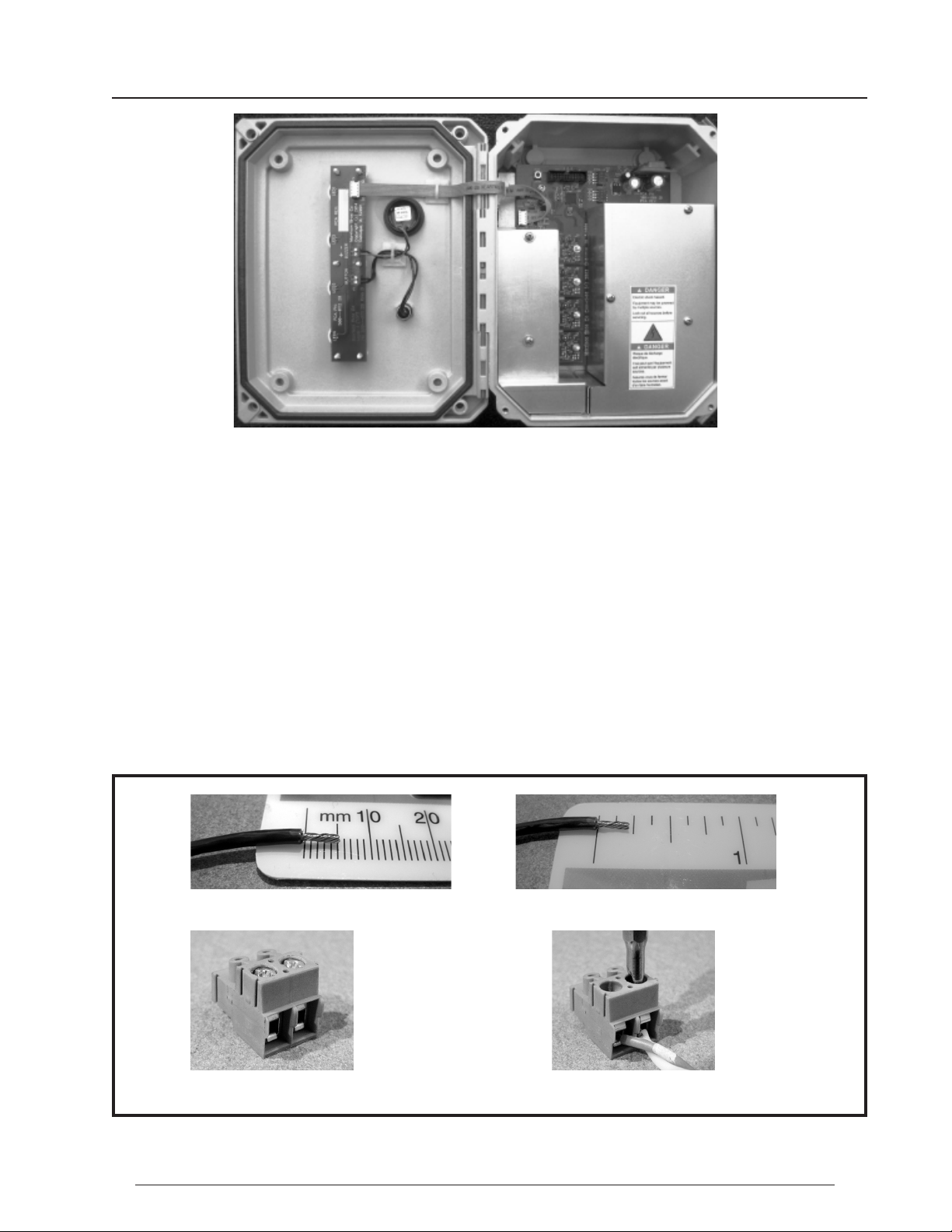
intrinsically safe section (see Figure 1).
2. Wiring
a. Run two oil and gas resistant wires from each input device to the location where the System
Interface will be mounted. Enter the enclosure through the LEFT bottom opening ONLY. If a
junction box is used, do NOT attach the wires of the input device(s) at this time. If the input device
is a Normally-Closed contact, connect the two wires together at the device end. If the device is a
Normally-Open contact, verify that the two wires are not connected to one another.
b. Connect the two wires from each input device to the two screw terminals for each channel input of
the Channel Input Connector (P1) for each Input Module (see Figure 2 and Figure 3).
Strip o about ¼ inch (5mm) of insulation from the wire and twist the ends of the wire.
The Channel Input Connector Insert the wire fully into the connector & snug the screw.
Figure 2 Wiring the Channel Input Connector
Intrinsically
Safe Section
Facilities
Section
Figure 1 Basic Layout of the 918AC

6
Morrison Bros. Co. ‑ Dubuque, IA ‑ 800‑553‑4840
918AC‑0142 PP
rev.10-20-2021
c. Verify that they are securely held in the connector by gently tugging on them.
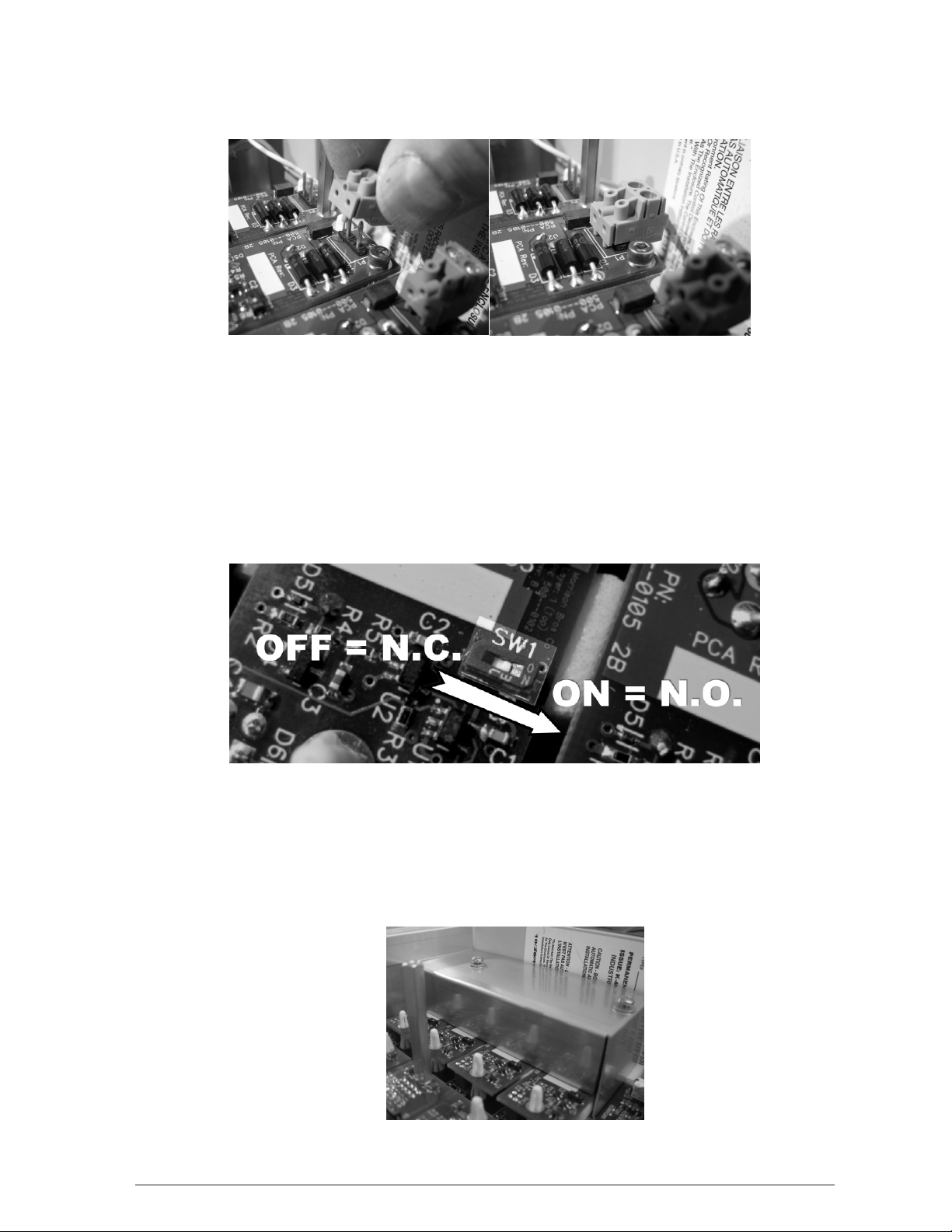
d. Plug the connector onto the Channel Input pins of the Dry Contact Input Module (see Figure 3).
Figure 3 Plug the Channel Input Connector onto the Channel Input Pins of the Alarm Circuit Board
e. Repeat steps 2 through 2.d for each remaining Input Channel.
3. Conguration
a. For Normally Open Contact Input Devices: If the input device to be connected to a particular Dry
Contact Input Module utilize normally open contacts, verify that the DIP switch on that module,
SW1, is in the “ON” position (see Figure 4).
b. For Normally Closed Contact Input Devices: If the input device to be connected to a particular
Dry Contact Input Module utilizes normally closed contacts, place the DIP switch on that module,
SW1, in the “OFF” position (see Figure 4).
Figure 4 Conguring Input Mode with SW1
4. Completion
a. Inspect all of the wiring to verify that it has been done properly. Correct any discrepancies and re-
inspect.
b. When the installation has passed inspection, reinstall the cover over the Intrinsically Safe section of
the System Interface.
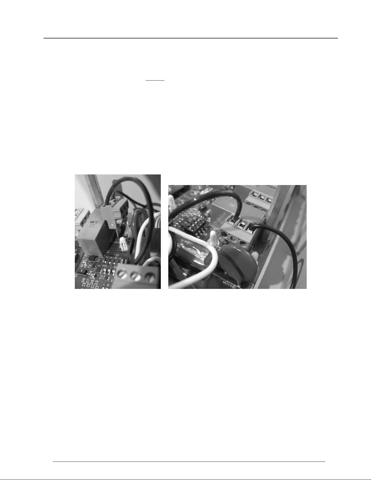
i. Place the cover in place and very loosely install the screws with their at washers as shown
in Figure 5
Figure 5 Installing the I.S. Cover

7
Morrison Bros. Co. ‑ Dubuque, IA ‑ 800‑553‑4840
918AC‑0142 PP
rev.10-20-2021
ii. Gently push the cover over to the wall of the enclosure and secure in place with the screws.
iii. Snug the screws down.
IMPORTANT NOTE: Verify that the power is shut o and the appropriate “Lockout/Tagout” (LOTO)
procedure is being adhered to before attempting any power wiring. This is true for
both the Power Input to the System Interface and the devices connected to the Output
Modules.
Facilities Section of the System Interface
NOTE:
A circuit breaker must be:
• included in this installation
• suitably located and easily reached
• marked as the disconnecting device for the 918AC being installed
1. Preparation
a. Remove the cover over the Facilities section of the System Interface (see Figure 1).
b. Remove and retain the three screws that secure the cover in place.
c. Remove the cover.
2. Wiring
a. Unplug the System Interface power input connector (J401/LNG) from the Motherboard.
b. Wire AC power from a dedicated circuit breaker, to the System Interface connector with the proper
wire per the appropriate electrical codes. Wiring shall be in accordance with the National Electric
Code and local regulation. Enter the enclosure through the center bottom hole ONLY.
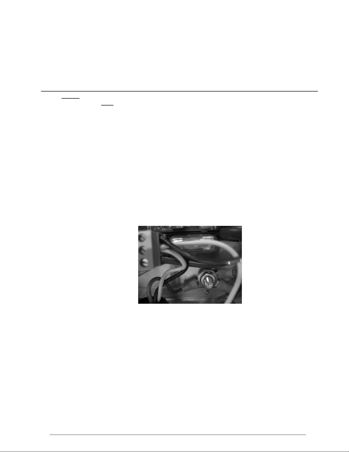
c. Be sure to connect input ground to the Intrinsic Safety Grounding Stud on the baseplate of the
Figure 918AC inside the enclosure (see Figure 6).
d. Connect the Intrinsic Safety Grounding Stud to an appropriate ground. Refer to NFPA 70, Article
504 for ground suitability.
Figure 6 Intrinsic Safety Grounding Stud
e. Strip the wire as shown in Figure 2.
f. Insert the wire fully into the power input connector & snug the screw
g. Repeat 2.e through 2.f for the remaining wires.
i. “L” → “Line” or HOT
ii. “N” → “Neutral”
iii. “G” → “Ground”
h. Verify that the wires are securely held in the connector by gently tugging on them.
i. Connect the input power to the Motherboard at J401/LNG being sure to pay attention to the
polarization of the connector.
j. DO NOT APPLY POWER TO THE SYSTEM INTERFACE.

8
Morrison Bros. Co. ‑ Dubuque, IA ‑ 800‑553‑4840
918AC‑0142 PP
rev.10-20-2021
Output Module(s) (if so equipped)
NOTE: See “Output Module Contact Rating” section of the “Specications” section of this document (on
page 2, above) for the contact rating for the output modules.
NOTE: The 918AC “outputs” do not provide any power of themselves; these are dry-contact switches only.
Supplied power runs through them to control your devices.
1. Wiring
a. Wiring shall be in accordance with the National Electric Code and local regulation. Enter the
enclosure from the right bottom hole only.
b. Strip the wire as shown in Figure 2.
c. Insert the wire fully into the connector & snug the screw
d. Repeat 1.b through 1.c above for the remaining wires as required by your application.
i. “C” → “COMMON”
ii. “NO” → “Normally-Open” contacts (C → NO only when relay is activated)
iii. “NC” → “Normally-Closed” contacts (C → NC only when relay is de-activated)
iv. Verify that the wires are securely held in the connector by gently tugging on them.
e. Connect the Output Connector to the Output Module connector, P1, as shown in Figure 7.
Figure 7 Connecting the Output Connector to the Output Module connector, P1
f. Repeat 1 through 1.e for each remaining Output Module.
2. Conguration
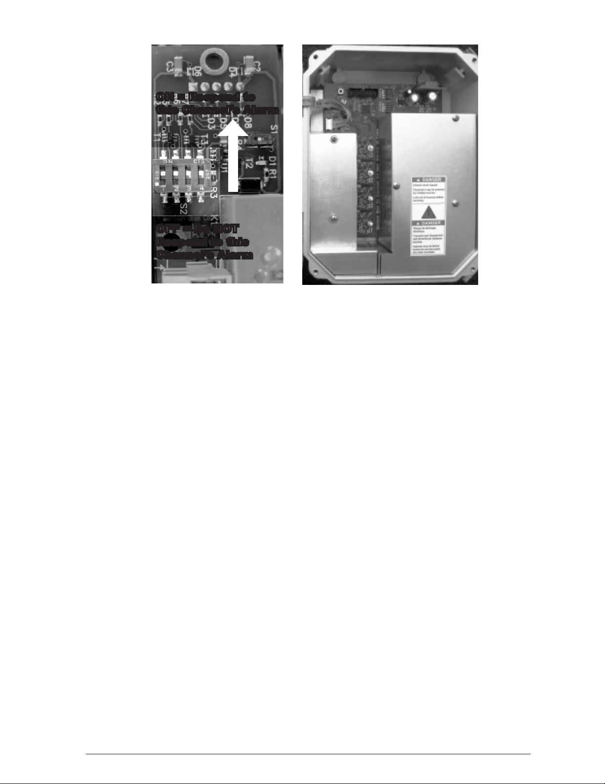
a. Alarm Channel – Congures a Dry Contact Output Module to respond to specic input channels.
Each Output Module may be congured to be activated by one or more input channels in any
combination. This is accomplished by setting DIP switch positions one through four of S2 either
ON (selecting a channel) or OFF (not selecting a channel).

9
Morrison Bros. Co. ‑ Dubuque, IA ‑ 800‑553‑4840
918AC‑0142 PP
rev.10-20-2021
Figure 8 - Output Module Alarm Channel Conguration
i. Locate the four position DIP switch, S2, on the Output Module to be congured
(see Figure 8).
ii. Place DIP switch Position One in the “ON” position to congure the output module to
respond to Input Channel One or in the “OFF” position to congure the Output Module to
not respond to Input Channel one.
iii. Place DIP switch Position Two in the “ON” position to congure the output module to
respond to Input Channel Two or in the “OFF” position to congure the Output Module to
not respond to Input Channel two.
iv. Place DIP switch Position Three in the “ON” position to congure the output module
to respond to Input Channel Three or in the “OFF” position to congure the Output Module
to not respond to Input Channel three.
v. Place DIP switch Position Four in the “ON” position to congure the output module to
respond to Input Channel Four or in the “OFF” position to congure the Output Module to
not respond to Input Channel four.
b. Relay Mode – Congure the Dry Contact Output Module as Normally-Deactivated or Normally-
Activated (fail-safe)
NOTE: Fail-Safe mode swaps the denition of the relay contact state. Normally-Open (NO) contacts become
Normally-Closed (NC) and Normally-Closed (NC) contacts become Normally-Open (NO).
ON = Respond to
this Channel’s Alarm
OFF = Do NOT
Respond to this
Channel’s Alarm
Channel 4
Channel 3
Channel 2
Channel 1

10
Morrison Bros. Co. ‑ Dubuque, IA ‑ 800‑553‑4840
918AC‑0142 PP
rev.10-20-2021
Figure 9 - Output Module Mode Conguration
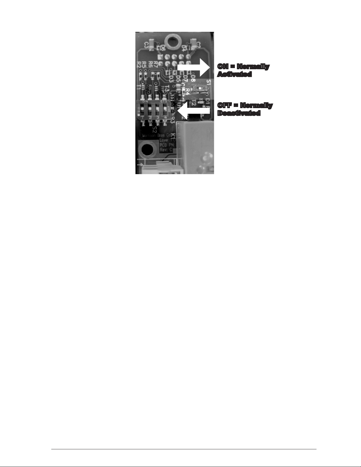
i. Locate the single position DIP switch, S1, on the Output Module to be congured (see
Figure 9).
ii. Place this DIP switch in the “OFF” position if the output is to be congured as Normally-
Deactivated.
iii. Place this DIP switch in the “ON” position if the output is to be congured as Normally-
Activated (Failsafe).
Completion
1. Inspect all of the wiring to verify that it has been done properly. Correct any discrepancies and re-inspect.
2. When the installation has passed inspection, reinstall the cover over the Facilities section of the System
Interface
a. Place the cover in place and install the three screws.
b. Snug the screws down.
ON = Normally
Activated
OFF = Normally
Deactivated
Autres manuels pour 918AC Series
1
Table des matières
Autres manuels Morrison Bros. co. Système de sécurité
Manuels Système de sécurité populaires d'autres marques

EDM
EDM Solution 6+6 Wireless-AE Manuel utilisateur

Highway Safety Group
Highway Safety Group EA401 Manuel utilisateur

Siren
Siren LED GSM Manuel utilisateur

Detection Systems
Detection Systems 7090i Instructions de montage
Se-Kure Controls
Se-Kure Controls MicroMini SK-4841 Manuel utilisateur

Siemens
Siemens FDM273 Manuel utilisateur