Morris 71531 Manuel utilisateur

Morris Products
53 Carey Rd Queensbury, NY 12804
INSTALLATION INSTRUCTION MANUAL
LED FLOOD LIGHT, 100-277VAC
Rev A Aug 2015
SERIES:
71531,71532,71533,71541,71542,71543,71544,71545,71551,71552,71553,71554,
71555, 71556, 71557, 71561, 71562, 71563, 71564, 71565, 71573, 71574, 71575, 71576, 71577,
71581, 71582, 71583, 71584, 71585, 71801, 71802, 71803, 71804, 71805, 71806, 71807, 71808,
71809, 71821, 71822, 71823, 71824, 71825, 71831, 71832, 71833, 71835, 71837, 71840, 71841,
71842, 71844, 71846, 71851, 71852, 71853, 71855, 71857, 71861, 71862, 71863, 71864, 71865,
71866, 71868, 71869
1. Introduction
This LED Flood light uses the latest in solid state lighting technology for long life,
low maintenance, and high efficiency.
An excellent alternative to traditional HID lighting. There are multiple installation methods,
suitable for different applications.
An internal power-factor-corrected switch-mode supply allows it to be used on
any nominal 100-277V, 60Hz AC voltage without any variation in light output.
Suitable for use in the following locations:
•
Ambient Temp: -20~+40°C
•
Wet Locations
2. Installation
For supply connections use wire rated for at least 90°C
“CAUTION – RISK OF SHOCK’’ and “DISCONNECT POWER BEFORE SERVICING”
Warning:
To avoid the risk of fire, explosion, or electric shock, this product should be installed,
inspected, and maintained by a qualified electrician only, in accordance with all applicable
electrical codes.
Warning:
To avoid electric shock:
•Be certain electrical power is OFF before and during installation and maintenance.
•Luminaire must be connected to a wiring system with an equipment-grounding conductor.
Warning:
To avoid explosion:
•Make sure the supply voltage is the same as the rated luminaire voltage.
•Do not install where the marked operating temperatures exceed the ignition temperature of
the hazardous atmosphere.
•Do not operate in ambient temperatures above those indicated on the luminaire nameplate.
•Keep lens tightly closed when in operation.
Morris Products
53 Carey Rd Queensbury, NY 12804
For supply connections use wire rated for at least 90°C
Installation Steps:
Refer to the following diagram when you install the fixture. Seven installation methods available,
Mount directly fix to a wall or other mounting surface or fix to a pole/post with a knuckle, trunion or slipfitter.
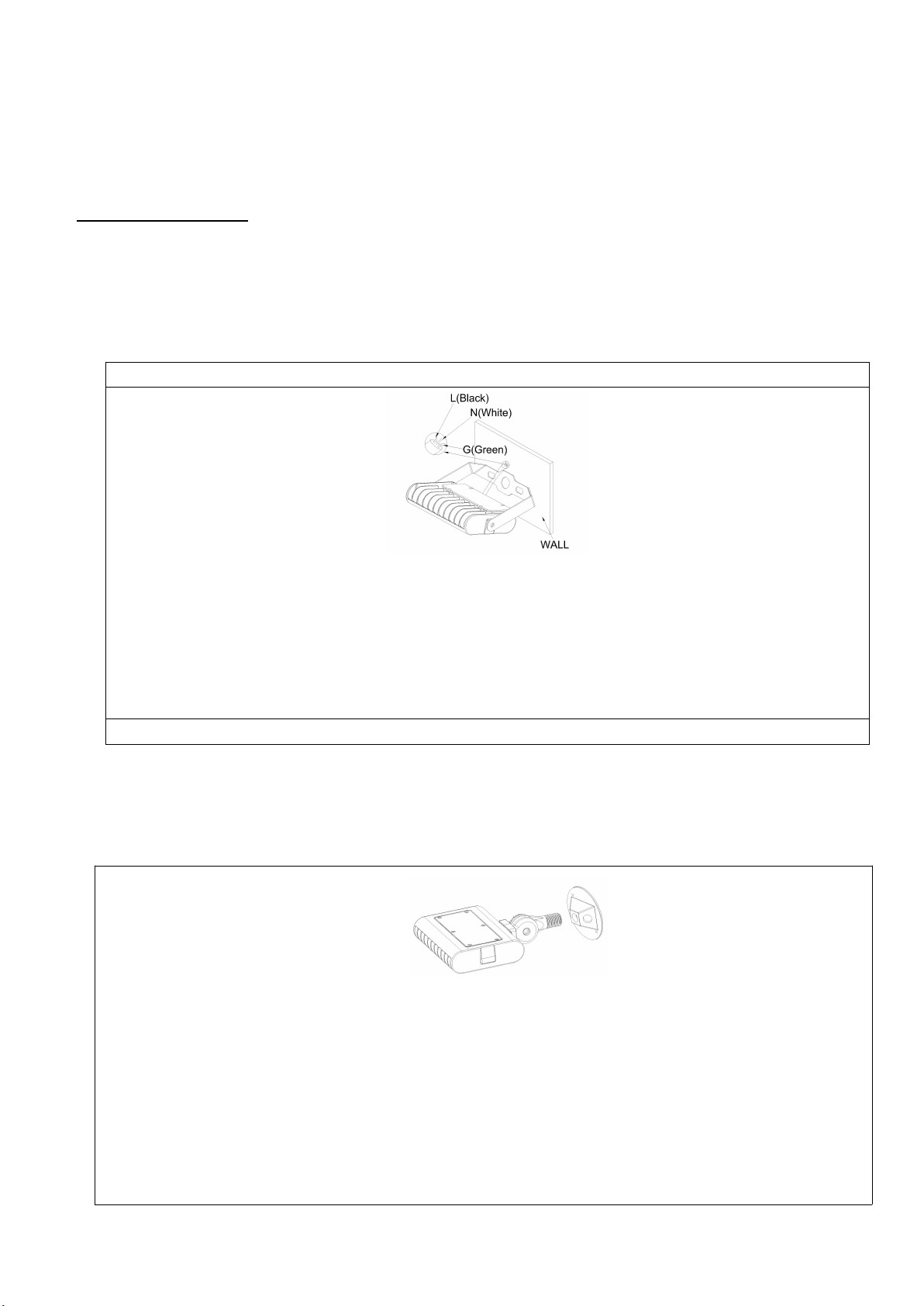
1. Mount directly fix to wall or other mounting surface with bracket: 71531, 71532, 71533, 71801, 71802,
71803, 71804, 71805, 71806, 71807, 71808, 71809
1. Use expansion bolts to secure the fixture on mounting surface.
2. Maintain enough slack length in wire leads to ensure adjusting angle unhindered.
Connect wires into wiring terminal:
white wire to“Neutral”terminal
black wire to“Live”terminal
green wire to “Ground” terminal
2. Mounting with a ½” knuckle for Models: 71551, 71552, 71553, 71554, 71555, 71556, 71557, 71821,71822,
71823,71824,71825
Secure service wire or conduit to the wiring compartment cover with 1/2” connector ( not provided ).
Connect white fixture wire to white supply wire, black fixture wire to black supply wire.
Service ground should be attached to green ground screw provided.
Ground must be properly attached to avoid the risk of electrical shock.
Use wire nuts, crimp-on lugs, or other approved devices to connect all wires, make sure connections are secure
and that no loose wire strands are sticking out of connectors
Secure wiring compartment cover to fixture, with black and white connections inside the wiring compartment.
Use UL and CUL Listed flexible steel waterproof conduit in trade sizes 1/2 and UL and CUL Listed
water-proof outlet box cove.

Morris Products
53 Carey Rd Queensbury, NY 12804
3. Mounting with a Slipfitter for Models:
71561, 71562, 71563, 71564, 71565,71840,71841,71842,71844,71846
Step 1
Adjust the fixture orientation by opening knockout at
fulcrum and turning the bolt.
Motion sensor or photocell can be installed in KO’s on
slipfitter mounting arm
Step 2
Use a tenon post of diameter 2.36” for mounting
and tighten screws completely.
You can open the side cover from the side
knockout
4. Mounting with Wall Mount for Models:
71581, 71582,71861,71862
Wall mounting method:
Install mounting plate on junction box, secure wall plate

Morris Products
53 Carey Rd Queensbury, NY 12804
Step 1
Drill the holes on the square pole or wall
Step 2
Adjust the fixture to the required orientation, tighten the
bolts completely
6. Mounting with Pole Arm for Models:
71573, 71574, 71575, 71576, 71577,71851,71852,71853,71855,71857
Secure pole mount arm to pole or wall with mounting hardware. Pole Arm has KO’s in top and bottom
for motion sensor or photocell requirements. Side cover is removable for access to wiring compartment.
5. Mounting with a Trunion for Models:
71541, 71542, 71543, 71544, 71545,71831,71832,71833,71835,71837

Morris Products
53 Carey Rd Queensbury, NY 12804
Same mounting method as #6 above - wall mounted fixing plate is mounted on the wall
with appropriate mounting hardware.
After installation:
check whether the lighting fixture is firmly secured.
check wiring for correctl connection.
Turn on the power, and check if the lighting fixture works well. If not, please turn off the power
and contact with local dealer.
7.Wall Mount installation
71583, 71584, 71585,71863,71864,71865,71866,71868,71869

FlatPanel Flood/Area Lights LED DRIVER Dimming Instructions
power voltage POWER Model 0-5V dimming 0-10V dimming PWM dimming
Time dimming
80W 100-277V EUC-085S200DT No yes No No
100-277V EUG-096S350DT yes yes yes yes
277-480V ESD-096S360DT No yes yes yes
100-277V EUG-150S350DT yes yes yes yes
277-480V ESD-150S560DT No yes yes yes
100-277V EUG-240S670DT yes yes yes yes
277-480V ESD-240S660DT No yes yes yes
100-277V EUC-320S490DT No yes No No
277-480V ESD-320S620DT No yes yes yes
SAFETY INFORMATION
1. Please make wiring according to the nameplate. Incorrect wiring will destroy the product. All the wires are
strictly prohibited to opposite polarity and shortcut. The dimming wires of dimmable driver are strictly
prohibited to connect high voltage (above 24V).
2. In order to avoid the bare wires connect the metal part or high voltage source, the dimming wires must be
isolated by proper method when the dimming function not used, for example wrapped by tape or sealed by
glue.
100W
150W
220W
300W
MORRIS Cat#s 71531 Thru 71585
71801 Thru 71898
Fixture Dimming Parameters

A4背面

Ce manuel convient aux modèles suivants
67
Table des matières
Autres manuels Morris Projecteur

Manuels Projecteur populaires d'autres marques

VIZULO
VIZULO Micro Martin Guide de l'utilisateur

EuroLite
EuroLite LED IP FL-100 SMD Manuel utilisateur

Cooper Wheelock
Cooper Wheelock XB12 Manuel utilisateur

Allen + Roth
Allen + Roth 17624-000 Manuel utilisateur

ADJ
ADJ 4 STAGE PAK Manuel utilisateur

Cooper Lighting
Cooper Lighting EGL91SW233 Manuel utilisateur


