Moeller MI4 Guide de configuration

Training Guide
MI4
Display Units and Operator Panels
05/01 AWB27-1302-GB
1st published 1998, edition 09/97
2nd published 1999, edition 08/99
3rd published 2001, edition 05/01
See list of revisions on Page II
© Moeller GmbH, Bonn
Author: Norbert Mausolf
Editor: Thomas Kracht
Translator: B & H, Terence Osborn
All brand and product names are trademarks
or registered trademarks of the owner
concerned.
All rights reserved, including those of the
translation.
No part of this manual may be reproduced in
any form (printed, photocopy, microfilm or
any otherprocess) or processed, duplicated or
distributed by means of electronic systems
without written permission of Moeller GmbH,
Bonn.
Subject to alterations without notice.

Warning!
Dangerous electrical voltage!
Before commencing the installation
●Disconnect the power supply of the
device.
●Ensure that devices cannot be
accidentally restarted.
●Verify isolation from the supply.
●Earth and short circuit.
●Cover or enclose neighbouring units that
are live.
●Follow the engineering instructions
(AWA) of the device concerned.
●Only suitably qualified personnel in
accordance with EN 50 110-1/-2
(VDE 0105 Part 100) may work on this
device/system.
●Before installation and before touching
the device ensure that you are free of
electrostatic charge.
●The functional earth (FE) must be
connected to the protective earth (PE) or
to the potential equalisation. The system
installer is responsible for implementing
this connection.
●Connecting cables and signal lines
should be installed so that inductive or
capacitive interference do not impair the
automation functions.
●Install automation devices and related
operating elements in such a way that
they are well protected against
unintentional operation.
●Suitable safety hardware and software
measures should be implemented for the
I/O interface so that a line or wire
breakage on the signal side does not
result in undefined states in the
automation devices.
●Ensure a reliable electrical isolation of
the low voltage for the 24 volt supply.
Only use power supply units complying
with IEC 60 364-4-41 (VDE 0100
Part 410) or HD 384.4.41 S2.
●Deviations of the mains voltage from
the rated value must not exceed the
tolerance limits given in the speci-
fications, otherwise this may cause
malfunction and dangerous operation.
●Emergency stop devices complying with
IEC/EN 60 204-1 must be effective in all
operating modes of the automation
devices. Unlatching the emergency-stop
devices must not cause restart.
●Devices that are designed for mounting
in housings or control cabinets must only
be operated and controlled after they
have been installed with the housing
closed. Desktop or portable units must
only be operated and controlled in
enclosed housings.
●Measures should be taken to ensure the
proper restart of programs interrupted
after a voltage dip or failure. This should
not cause dangerous operating states
even for a short time. If necessary,
emergency-stop devices should be
implemented.
●Wherever faults in the automation
system may cause damage to persons
or property, external measures must be
implemented to ensure a safe operating
state in the event of a fault or malfunction
(for example, by means of separate limit
switches, mechanical interlocks etc.).

II
08/99 AWB 27-1302 GB
List of revisions for AWB 27-1302 GB
Edition Page Description New Modifica-
tion
Removed
09/97 43 Figure ҂
08/99 entire
AWB
Revision of MI 4 Configurator, Version 1.1 ҂
05/01 5 Sucosoft S40 ҂
6, 10,
11, 20,
35, 36,
37,
Figures ҂

1
05/01 AWB27-1302-GB
Contents
1Introduction 3
2 Example for a Text Operator Panel 5
Overview 6
Creating the project 6
Defining data fields 9
Transferring the project to the MI 4 12
Creating and transferring the PLC program 13
Testing the project 17
Expanding the project 17
Testing the expanded project 23
3 Example for Touch Operator Panel 25
Overview 26
Creating the project 29
Creating date and time fields 30
Defining a touch cell with macro function 31
Creating data fields 34
Defining bargraphs 37
Transferring the project to the MI 4 38
Creating and transferring the PLC test
program 39
Testing the project 43
Installing touch cells for page changeover 43
Creating an illuminated pushbutton touch cell 45
Defining dynamic graphics 47
Defining message texts 49
Testing the expanded project 51
Index 53

2
05/01 AWB27-1302-GB

3
05/01 AWB27-1302-GB
1 Introduction
This brief introduction will show you, in the form of
two examples, how you can set up your panel with
the aid of the MI4 configuration software. Working
through the examples step by step is an excellent
way of familiarizing yourself with the program.
The MI4 range consists of Text Operator Panels,
Graphic Operator Panels and Touch Panels with the
MI4 configuration software (“MI4-CFG-1”) you can
configure all of the panels in the MI4 series to your
specifications.
The first practice example uses a Text Operator
Panel for configuration, the second example uses a
Touch Panel. In both of these examples the projects
are configured and transferred to the MI4 in question.
If you have a PLC connected you can test the
projects afterwards via the PLC connection. A basic
knowledge of Sucosoft S40 is a prerequisite.You will
in this way learn how a project is structured and how
to work with the MI4 configuration software.
The menu bar of the MI4 Configurator will adapt itself
to the particular MI4 panel selected. Menu items that
are not required are not displayed.

4
05/01 AWB27-1302-GB

5
05/01 AWB27-1302-GB
2 Example for a Text Operator Panel
In this example you will become acquainted with the
functions used for configuring an MI4 Text Operator
Panel. In conjunction with a PLC you will be able to
test the functions of the projects afterwards. The MI4
panel is connected to the PLC via Suconet K.
Configuring the work area
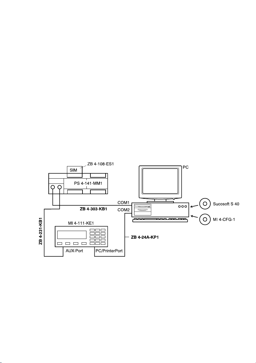
The connection diagram for the project shows all of
the devices, connection points and connecting
cables required for the practice example. Instead of
the MI4-111-KE1 you could equally use a different
MI4 Text Operator Panel.
Before the MI4 can be configured the MI4-CFG-1
configuration software and the “Sucosoft S40
software for PLC programming must be installed on
the PC.

Example for a Text
Operator Panel
6
05/01 AWB27-1302-GB
Overview The practice example is carried out in seven steps:
Creating the project
Defining data fields
Transferring the project to the MI4
Creating and transferring the PLC program
Testing the project
Expanding the project
Testing the expanded project.
Creating the project Start the MI4 Configurator. The program window
with its main menu and icon bars is displayed.
왘Under ‹Project ➞Panel Setup...›select the
panel model MI4-111-KE1. The MI4-111-KE1 is
provided display size of 4 x 20 characters.
왘Under ‹Project ➞Change Controller Driver...›
select the driver “Suconet K K-M”.

Creating the project
7
05/01 AWB27-1302-GB
The driver you have selected will be displayed on the
status bar at the bottom of the screen.
왘Under ‹Project ➞Controller Setup...›select the
PLC with which you want to run the MI4, e.g. the
PS4-141-MM1
왘Set the communication buffer size for input and
output at 20. These settings must agree with
those that you make later in the Sucosoft S40
Topology Configurator.
Under Panel ID the slave number is entered:
Slave 1 in this instance.
Following these preliminary settings the configurator
will present a display field on the screen which
corresponds to the MI4 display.
You can increase or decrease the size of the display
field by clicking on the following icons:
Zoom in
Zoom out
Autres manuels pour MI4
2
Table des matières
Autres manuels Moeller Équipement d'enregistrement
Manuels Équipement d'enregistrement populaires d'autres marques

Strymon
Strymon NIGHTSKY Manuel utilisateur

Mitsubishi Electric
Mitsubishi Electric 16CH DIGITAL RECORDER DX-TL5000U Manuel utilisateur

Tews Technologies
Tews Technologies TPMC465 Manuel utilisateur

Honeywell
Honeywell Excel 50 Manuel utilisateur

SeaLevel
SeaLevel COMM+8.LPCI Manuel utilisateur

Arturia
Arturia AUDIOFUSE STUDIO Manuel utilisateur