MIXHITS AUDIO MRT-35M Manuel utilisateur
Please follow the instructions in this manual to obtain the optimum results from this unit.
We also recommend that you keep this manual handy for future reference.
OPERATION MANUAL
MRT-35M
Mixer Amplifer
AUDIO
Lorem ipsum
MRT-35M
MIXER AMPLIFER
TABLE OF CONTENTS
1. SAFETY PRECAUTIONS
2.
3. FEATURES
4. FUNCTIONS
5.
6. CONNECTION DIAGRAM
7.
8.
GENERAL DESCRIPTION
OPERATION
Ω
.
BLOCK DRAWING
SPECIFICATION
Be sure to read the instructions in this section carefully before use.
Make sure to observe the instructions in this manual as the conventions of safety symbols and messages
regarded as very important precautions are included.
We also recommend you keep this instruction manual handy for future reference.
Safety Symbol and Message Conventions
Safety symbols and messages described below are used in this manual to prevent bodily injury and property
damage which could result from mishandling. Before operating your product, read this manual first and
understand the safety symbols and messages so you are thoroughly aware of the potential safety
Indicates a potentially hazardous situation which, if mishandled, could
result in death or serious personal injury.
Indicates a potentially hazardous situation which, if mishandled, could
result in moderate or minor personal injury, and/or property damage.
When Installing the Unit
• Do not expose the unit to rain or an environment
where it may be splashed by water or other liquids,
as doing so may result in fire or electric shock.
• Use the unit only with the voltage specified on
the unit. Using a voltage higher than that which is
specified may result in fire or electric shock.
• Do not cut, kink, otherwise damage nor modify
the power supply cord. In addition, avoid using
the power cord in close proximity to heaters, and
never place heavy objects including the unit itself
on the power cord, as doing so may result in fire
or electric shock.
• Be sure to replace the unit's terminal cover after
connection completion. Because high voltage is
applied to the speaker terminals, never touch
these terminals to avoid electric shock.
• Be sure to ground the safety ground (earth)
terminal to avoid electric shock. Never ground to a
gas pipe as a catastrophic disaster may result.
• Avoid installing or mounting the unit in unstable
locations, such as on a shaky table or a slanted
surface. Doing so may result in the unit falling
down, causing personal injury and/or property
damage.
When the Unit is in Use
Should the following irregularity be found during
use, immediately switch off the power, disconnect
the power supply plug from the AC outlet and
contact your Mixhits Audio dealer. Do not attempt to
operate the unit in this condition as this may cause
fire or electric shock.
• If you detect smoke or an odor from the unit.
• If water or any metallic object gets into the unit
• If the unit falls, or the unit case breaks
• If the power supply cord is damaged.
• If it is malfunctioning (no sound.)
• To prevent a fire or electric shock, never open or
remove the unit case as there are high voltage
components inside the unit. Refer all servicing to
your Mixhits Audio dealer.
• Do not place cups, bowls, or other containers of
liquid or metallic objects on top of the unit. If they
accidentally spill into the unit, this may cause a fire
or electric shock.
• Do not insert or drop metallic objects or flammable
materials in the ventilation slots of the unit's cover,
as this may result in fire or electric shock.
1. SAFETY PRECAUTIONS
3

An all-pole mains switch with a contact separation of at least 3 mm in each pole shall be incorporated in
the electrical installation of the building.
When Installing the Unit
• Never plug in nor remove the power supply
plug with wet hands, as doing so may cause
electric shock.
• When unplugging the power supply cord, be sure
to grasp the power supply plug. Never pull on the
cord itself. Operating the unit with a damaged
power supply cord may cause a fire or electric
shock.
• When moving the unit, be sure to remove its
power supply cord from the wall outlet. Moving the
unit with the power cord connected to the outlet
may cause damage to the power cord, resulting in
fire or electric shock. When removing the power
cord, be sure to hold its plug to pull.
• Do not block the ventilation slots in the unit's
cover. Doing so may cause heat to build up inside
the unit and result in fire.
• Avoid installing the unit in humid or dusty
locations, in locations exposed to the direct
sunlight, near the heaters, or in locations
generating sooty smoke or steam as doing
otherwise may result in fire or electric shock.
When the Unit is in Use
• Do not place heavy objects on the unit as this
may cause it to fall or break which may result in
personal injury and/or property damage. In
addition, the object itself may fall off and cause
injury and/or damage.
• Make sure that the volume control is set to the
minimum position before the power is switched on.
Loud noise produced at high volume when power is
switched on can damage hearing.
• Do not operate the unit for an extended period of time
with the sound distorting. This is an indication of a
malfunction, which in turn can cause heat to generate
and result in a fire.
• If dust is allowed to accumulate in the unit over a
long period of time, a fire or damage to the unit
may result. Contact your Mixhits Audio dealer to
schedule a cleaning of the unit.
• If dust accumulates on the power supply plug or
in the wall AC outlet, a fire may result. Clean it
periodically. In addition, insert the plug in the wall
outlet securely.
• Switch off the power, and unplug the power
supply plug from the AC outlet for safety
purposes when cleaning or leaving the unit
unused for several days. Doing otherwise may
cause a fire or electric shock.
4
SAFETY PRECAUTIONS
MIC 1 MIC 2/AUX 1 MIC 3/AUX 2 BASS TREBLE
0
4
6
2
8 10 12
14
16
18
20
MASTER VOLUME
5
0
1
3
4 6
7
2 8
9
10
5
0
1
3
4 6
7
2 8
9
10
5
0
1
3
4 6
7
2 8
9
10 -10 +10 -10 +10
ON
OFF
POWER
The MRT-35M is a tabletop constant voltage amplifier. It's small size and light weight is designed to deliver
reliable music and paging in many places such as small offices, quick server restaurants, retail, and
hospitality locations.
2. GENERAL DESCRIPTION
5
3. FEATURES
1. Tabletop design, black plate, high-grade professional knobs.
2. 3 MIC level inputs, 2 AUX line level inputs,(one 1/4" port, one RCA port).
3. 1 MIC volume control, 2 MIC/AUX volume controls.
4. MIC1 takes priority to other audio inputs.
5. There are separate treble and bass adjustment knob.
6. One MIC2 / AUX1 selector switch, one MIC3 / AUX2 selector switch.
7. 35W constant resistance 4~16 ohms output and constant voltage 70V output.
8. Power supply with ~110-240V 50/60Hz, with power signal light.
4. FUNCTIONS
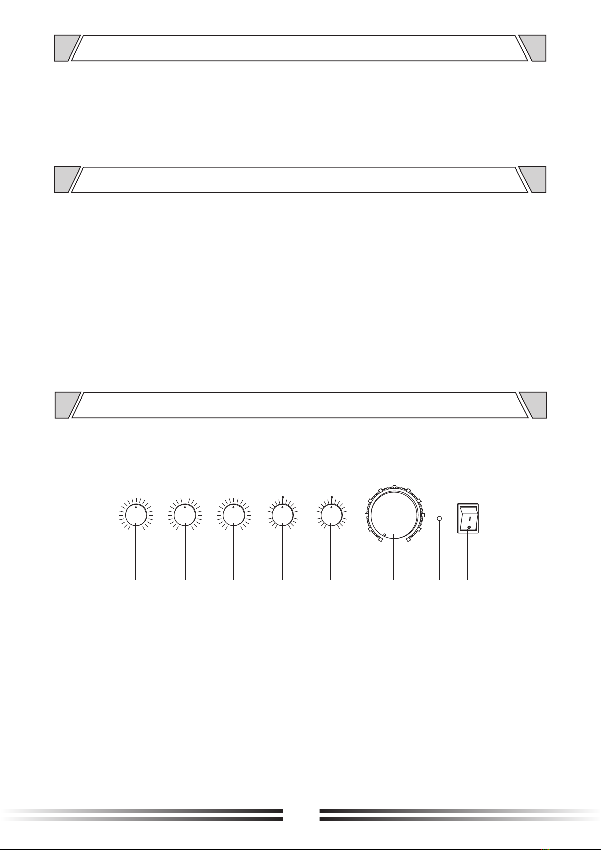
4.1 FRONT PANEL
1. MIC1 volume control.
2. MIC2/AUX1 volume control.
3. MIC3/AUX2 volume control.
4. BASS
Adjust bass response. Rotate clockwise to
increase bass output and counter clockwise
to reduce it.
5. TREBLE
Adjust treble response. Rotate clockwise to
increase treble output and counter clockwise
to reduce it.
6. MASTER VOLUME
Master volume controls all inputs.
7. POWER
The power LED illuminates when power is on.
8. ON/OFF POWER SWITCH
1 2 345 6 78
NC
NC
MIC3 AUX1 MIC2 MIC1
AUX2
L
R
AUX2 MIC3 AUX1 MIC2
OUTPUT
COM
4-16Ω
70V 100V
MIC3 AUX1 MIC2 MIC1
AUX2
L
R
AUX2 MIC3 AUX1 MIC2
OUTPUT
COM
4-16Ω
70V 100V
BATT SUPPLY
24V
5A
4. FUNCTIONS
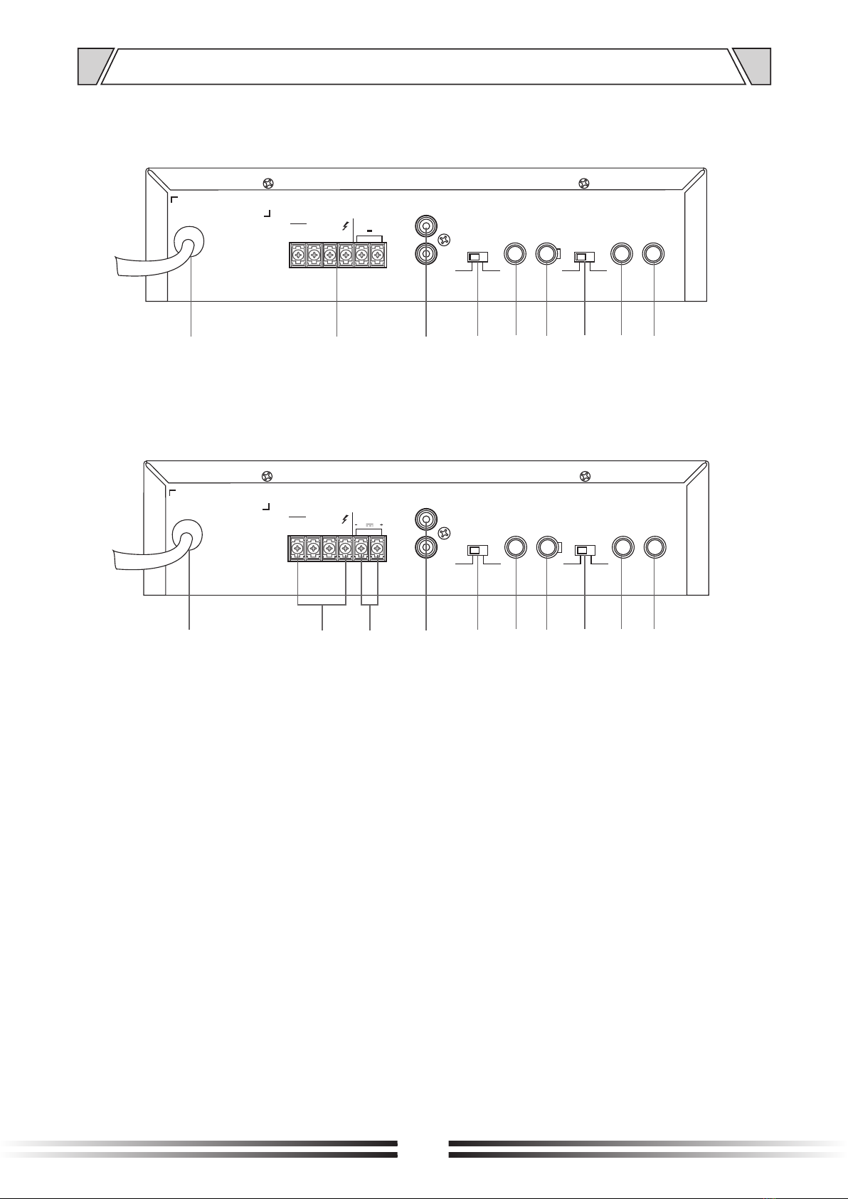
4.2 REAR PANEL
6
4.3 REAR PANEL(+24V)
11. Optional DC24V input
12. AUX2 Signal unbalanced input port
13. AUX2/MIC3 selector switch
14. MIC3 Signal unbalanced input port
15. AUX1 Signal unbalanced input port
16. AUX1/MIC2 selector switch
17. MIC2 Signal unbalanced input port
18. MIC1 Signal unbalanced input port
9. AC power input
10. OUTPUTS
To utilize 4~16Ω speakers connect the
positive wire to the 4~16Ω terminal and
negative wire to COM. To utilize 70V or
100V speakers connect the positive wire to
70V or 100V and the negative wire to COM.
Do not mix and match 4~16Ω speakers with
70/100V speakers.
9 10 12 13 14 15 16 17 18
9 10 12 13 14 15 16 17 18
11
NC
NC
MIC3 AUX1 MIC2 MIC1
AUX2
L
R
AUX2 MIC3 AUX1 MIC2
OUTPU T
COM
4-16Ω
70V 100V
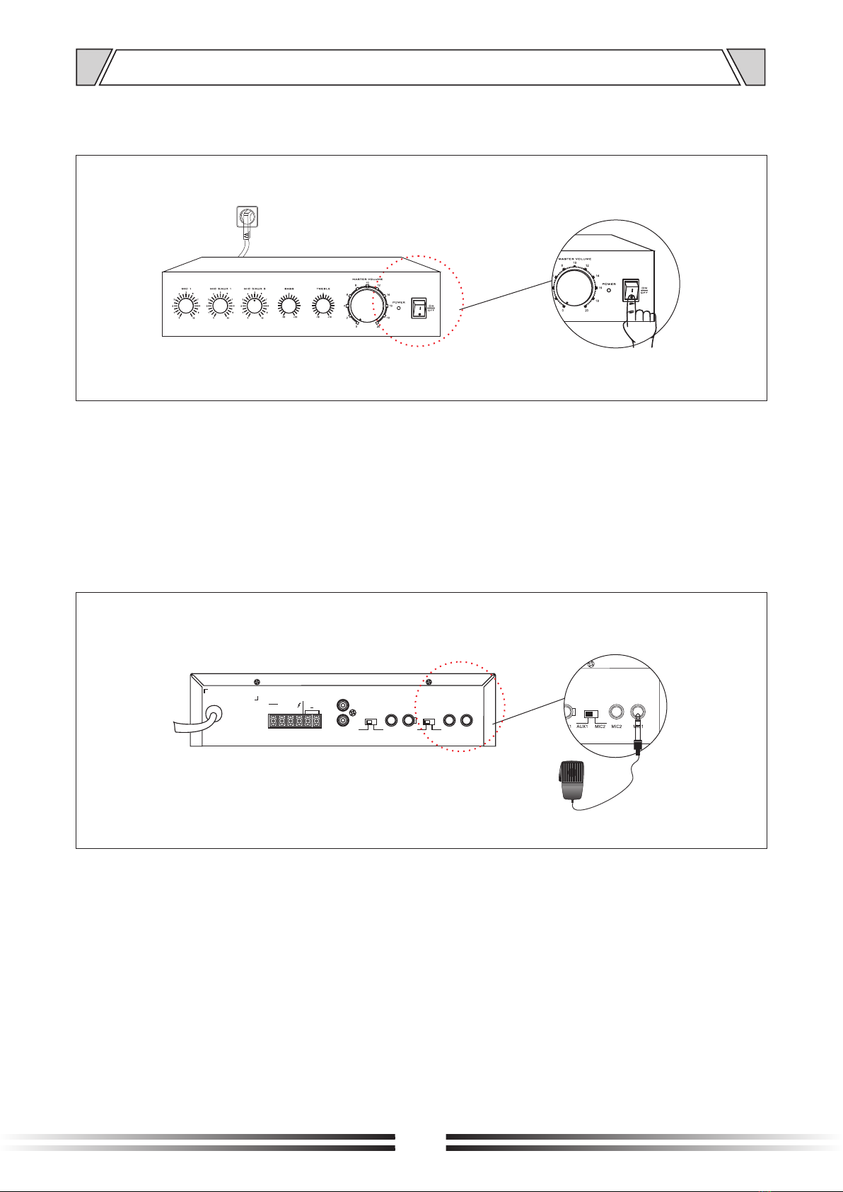
5.OPERATION ILLUSTRATION
5.1
5.2
Power LED
Power switch
Figure 5.3
MIC 1 is an unbalanced 1/4" input. Before using MIC 1 turn the input gain to the lowest setting then raise it slowly
to achieve the desired volume.
5.3 MIC1 input(1/4")
Figure 5.1/5.2
When the power switch is "ON" the power indicator is lit (red).
When the power switch is "OFF", the power indicator will go off.
7
NC
NC
MIC3 AUX1 MIC2 MIC1
AUX2
L
R
AUX2 MIC3 AUX1 MIC2
OUT PU T
COM
4-16Ω
70V 100V
OPERATION ILLUSTRATION
8
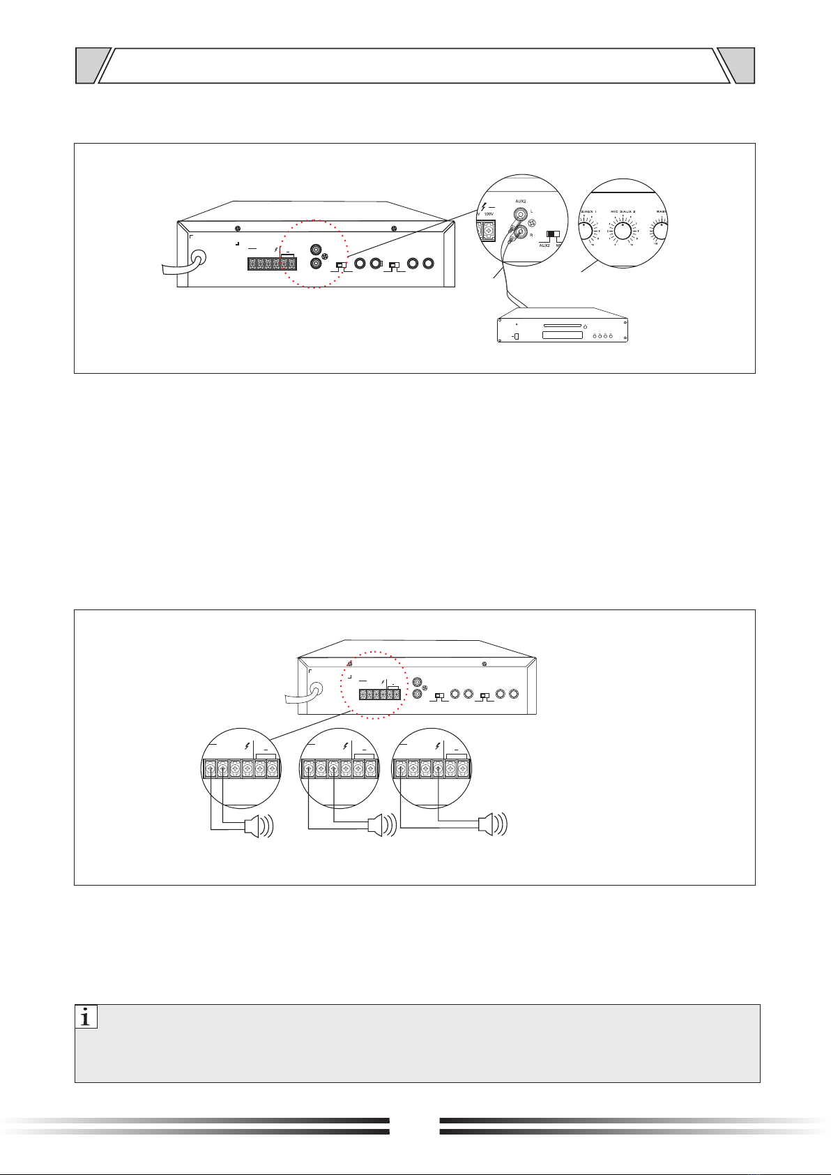
5.4 AUX2 input
Figure 5.4
AUX2 RCA inputs are summed to mono and gain is controlled by using the MIC3 / AUX2 knob. To use AUX2
the selector switch must be set to AUX2. AUX2 and MIC3 can not be used simultaneously.
Figure 5.5
To utilize 4~16Ω speakers connect the positive wire to the 4~16Ω terminal and negative wire to COM. To utilize
70V or 100V speakers connect the positive wire to 70V or 100V and the negative wire to COM. Do not mix and
match 4~16Ω speakers with 70/100V speakers. Do not exceed 35 watts total load. It is strongly suggested to
utilize no more than 80% of the rated power to allow for headroom.
安 全 须 知
Note:
1. Pay attention to the positive and negative connection..
2. Please be sure to install the terminal protecting cover when you're finished.
Speaker terminals have high voltage. Do not touch to avoid electric shock.
POWER
ON
OFF
PLAY STOP NEXTPREVIOUS
OPEN
CLOSE
CD Volume control
NC
NC
OUTPUT
COM
4-16Ω
70V 100V
NC
NC
OUTPUT
COM
4-16Ω
70V 100V
NC
NC
MIC3 AUX1 MIC2 MIC1
AUX2
L
R
AUX2 MIC3 AUX1 MIC2
~AC INPUT
120V 50-60Hz 80W
OUT PUT
COM
4-16Ω
70V 100V
5.5 -16Ω4 /70V/100V speaker output
4-16Ωspeaker
NC
NC
OUTPUT
COM
4-16Ω
70V 100V
...... ......
70Vspeaker 100Vspeaker
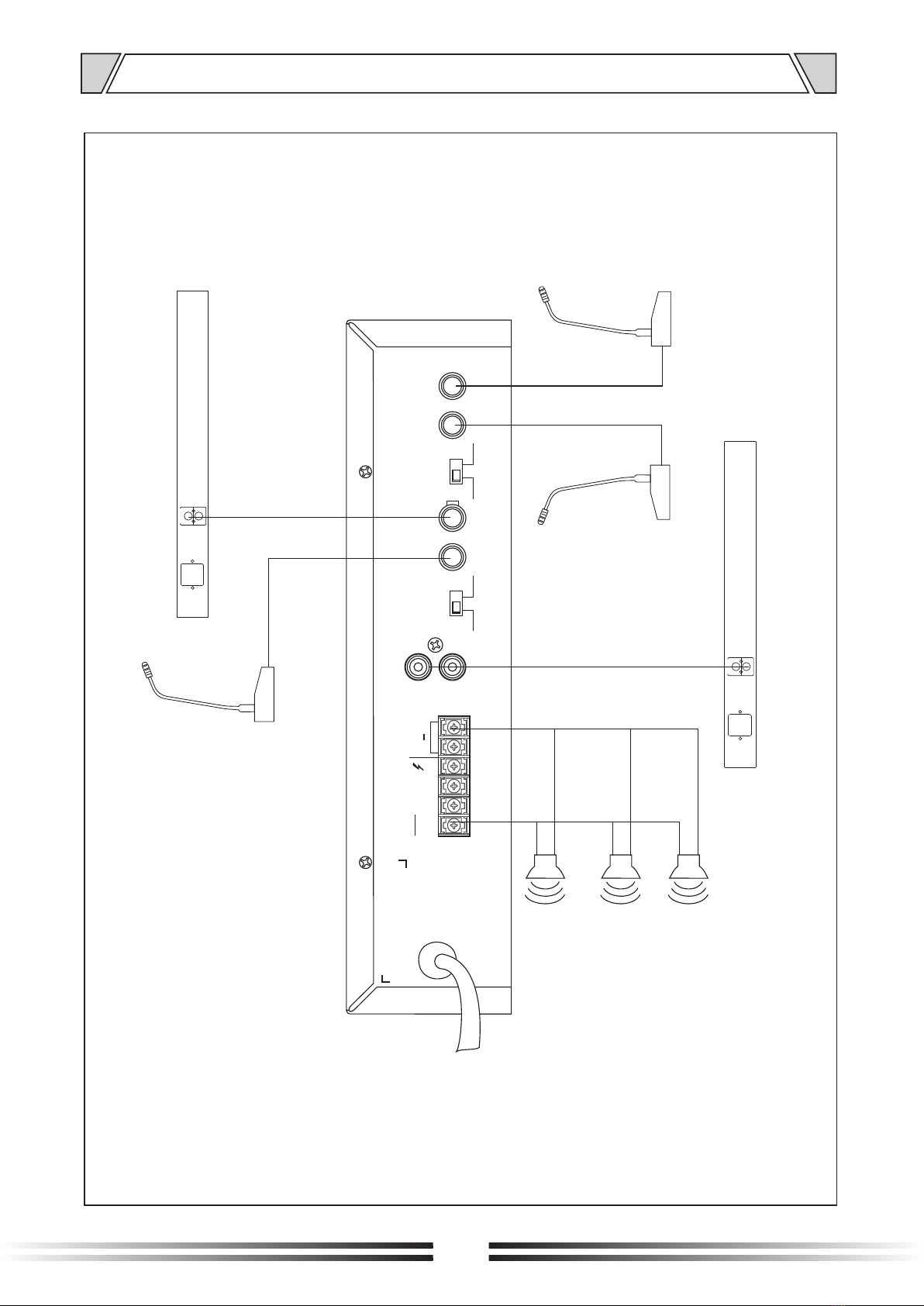
6.CONNECTION DIAGRAM
9
NC
NC
MIC3 AUX1 MIC2 MIC1
AUX2
L
R
AUX2 MIC3 AUX1 MIC2
OUTPUT
COM
4-16Ω
70V 100V
AUDIO OUT
RR
LL
Audio Source
MIC 1
MIC 2
MIC 3
AUDIO OUT
RR
LL
speaker
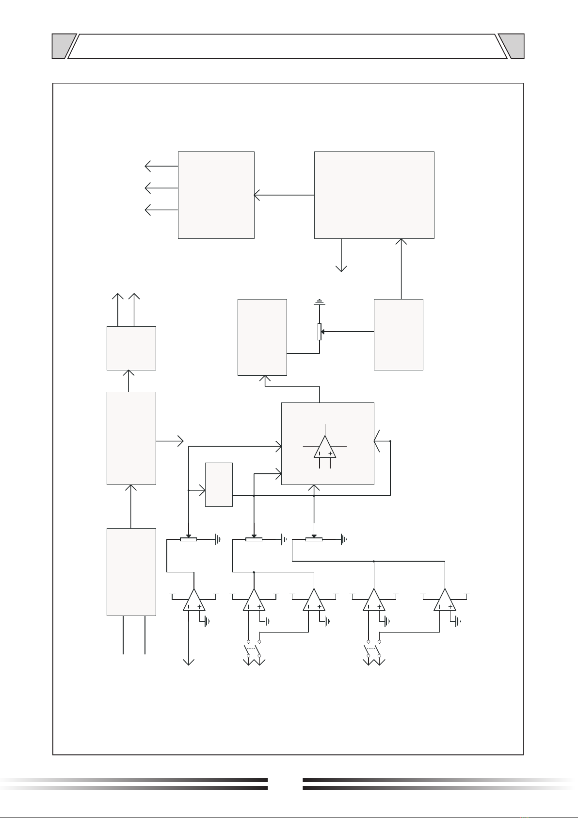
7. BLOCK DIAGRAM
10
ON/OFF switch
AC Power input
Rectifier filter circuit
+24V
+8V
-8V
AR
OPAMP
AR
OPAMP
AR
OPAMP
AR
OPAMP
Limiting circuit
VR1
VR2
VR3
AR
OPAMP
+8V
-8V
-8V
+8V
VCC
VCC
+8V
-8V
+8V
-8V
MIC1
MIC2
MIC3
AUX2
K1
AUX1
K2
Bass/treble circuit
Power amplifier
Audio transformer
4-16
Ω
70V 100V
VR4
Master volume
Hybrid amplifier circuit
+24V
MIC2/AUX1
volume
MIC1
volume
MUTE
MIC3/AUX2
volume
Voltage
stabilizing
circuit
Table des matières
Autres manuels MIXHITS AUDIO Amplificateur


