MiSolar MMC6K-G Manuel utilisateur

PV Grid Tie Inverter
MMC6K-G MMC8K-G
MMC10K-G
User manual

Contents Contents
1. Introduction
1.1 Appearance Introduction
1.2 Parts list
2. Safety warnings and instructions
2.1 Safety signs
2.2 Safety instructions
2.3 Notes for using
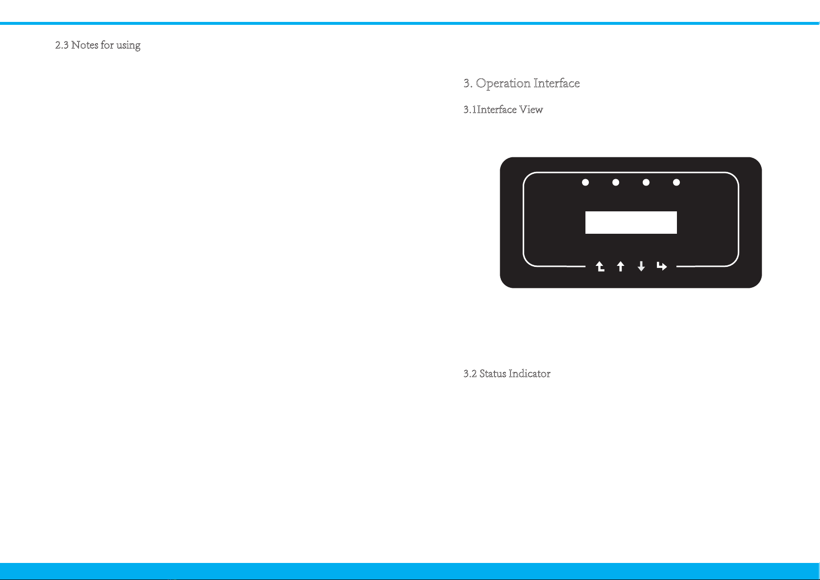
3. Operation Interface
3.1 Interface View
3.2 Status Indicator
3.3 Buttons
3.4 LCD Display
4. Product installation
4.1 Select installation location
4.2 Inverter Installation
5. Electrical Connection
5.1 DC input terminal connection
5.2 AC input terminal connection
5.3 The connection of the ground line
5.4 Inverter monitoring connection
6. Startup and Shutdown
6.1 Start up the inverter
6.2 Inverter Shutdown
7. General Operation
7.1 The initial interface
7.2 Device information
7.3 Fault Record
7.4 ON/OFF setting
7.5 Parameter setting
7.5.1 System Param
7.5.1.1 Time set
7.5.1.2 Language set
7.5.2 Running Param
7.5.3 Protect Param
- 1 - - 33 -
- 33 -
- 34 -
- 36-
- 37 -
- 1 -
- 2 -
- 3 -
- 3 -
- 3 -
- 5 -
- 6 -
- 6 -
- 6 -
- 7 -
- 7 -
- 8 -
- 8 -
- 10 -
- 12 -
- 12 -
- 15 -
- 18 -
- 18 -
- 20 -
- 21 -
- 21 -
- 22 -
- 22 -
- 23 -
- 25 -
- 26 -
- 26 -
- 28-
- 29 -
- 29 -
- 29 -
- 29 -
…………………………………………………………
…………………………………………
………………………………………
…………………………………………………………
…………………………………………………………
………………………………………………
……………………………………
…………………………………………………
…………………………………………………………
………………………………………………………
…………………………………………………
……………………………………………………
……………………………………………………
……………………………………………………
……………………………………………………
………………………………………………………
……………………………………………………
……………………………………………………
…………………………………………………………
…………………………………………
…………………………………………
………………………………………
………………………………………
………………………………………………
………………………………………………………
…………………………………
……………………………………
………………………………………………
………………………………………………
………………………………………………
………………………………………………
……………………………………………………
…………………………………………………
………………………………………………
………………………………………………………
……………………………………………………
……………………………………………………
……………………………………………………
………………………………………………
Contents
8. Repair and Maintenance
9. Error information and processing
9.1 Error code
9.2 Troubleshooting
10. Specification

1. Introduction
Photovoltaic Grid-connected System
Application of inverter in photovoltaic power system
1.1 Appearance Introduction
1.2 Parts list
Three Phase String Power Inverter can convert solar panel DC power into
AC power which can directly input to the grid. Its appearance as shown below.
These models contain MMC6K-G、MMC8K-G、MMC10K-G.
Pic1.1 Front view Pic1.2 Bottom view
Pic1.3 Accessories drawing
1.1 Parts list
Description
PV grid tie Inverter
Wall mounting bracket
Mounting stainless steel screw M4*12
AC power connectors
DC power connectors(including Insert spring)
Stainless steel Collision boltM6*80
Square hole sealing plate(Wi-Fi Function selection)
User manual
Wifi-Plug(optional)
No
1
2
3
4
5
6
7
8
9
1
1
4
1
2pairs
4
1
1
1
Qty
Please check according to following table, to see whether all the parts were
included in the packaging:
1
67
234 5
89
ABCD
E
Serial number Description
A
B
C
D
E
Inverter
Metering device
PV strings
Power grid
Family load
- 1 - - 2 -
8
DC SWITCH
ON
OFF
RS232485
limiter
RS485
ACDC AlarmNormal
ACDC AlarmNormal
ACDC AlarmNormal

2. Safety warnings and instructions
2.1 Safety signs
=GXTOTM
Improper use of the inverter will cause electric shock and burn. During installation
and maintenance. Please strictly follow the instructions on this manual. Please read
the user manual carefully before using the inverter. And please keep the instructions
properly for afterwards use.
Safety signs are used to emphasize potential safety risk and important safety
information. The manual includes below sings:
2.2 Safety instructions
Safety warning——Indifference of the signs in the manual
may cause injure or even death.
9NUIQ.G`GXJ
Shock warning sign——Incorrect follow of this sign may get
shocked.
9GLKZ_.OTZ
Prudent operation——Incorrect follow of the safety
operation hints in this manual may cause inverter defective.
.OMN:KSVKXGZ[XK.G`GXJ
Inverter’s local temperature may exceed 80℃ while
under operating. Please do not touch the inverter’s surface.
=GXTOTM
Electrical installation of the inverter must conform to the
safety operation rules of the country or local area.
=GXTOTM
Inverter is non-isolated topology structure, hence must
insure DC input and AC output are electrical isolated before
operating the inverter. Strictly prohibit ground the positive
and negative poles of the PV string. Otherwise it will
damage the inverter.
9NUIQ.G`GXJ
Prohibit disassembling inverter case. There existing shock
hazard, may cause serious injury or death, please ask
qualified person to maintenance.
9NUIQ.G`GXJ
When PV module is exposed to sunlight, The output will
generate DC voltage.Prohibit touching to avoid shock
hazard.
9NUIQ.G`GXJ
After disconnecting the input and output of the inverter,
it takes at least 5 minutes for the inverter to completely
release the residual energy and wait for at least 5 minutes
before it can be overhauled.
.OMN:KSVKXGZ[XK.G`GXJ
Inverter’s local temperature may exceed 80℃ while under
operating. Please do not touch the inverter’s surface.
- 3 - - 4 -
2.3 Notes for using
3.2 Status Indicator
3. Operation Interface
3.1Interface View
1. Inverter should be installed and maintained by qualified person under local
standard regulations.
2. It must disconnect the AC side first, then disconnect DC side before doing
installation and maintenance, after disconnecting, please wait at least 5 mines
to avoid get shocked.
3. Local temperature of the inverter may exceed 80 ℃ while under operating.
Do not touch to avoid get injured.
4. All electrical installation must accord with local electrical standards, and after
obtaining the permission of the local power supply department, the
professionals can connect the inverter to the grid.
5. Please take appropriate anti-static measure.
Pic 3.1 Panel
6. Please install where children can not touch.
8. Don’t insert and remove AC and DC terminals when the inverter is in
normal operation.
9. The DC input voltage of the inverter must not exceed the maximum input
voltage of the model.
The inverter panel has 4 indicators, the left one is DC output indicator(green),
indicates normal DC input power status. Beside is the AC indicator(green),
indicates normal AC connecting status. Next is the operating indicator(green)
indicates normal output. The right indicator is alarm(red), indicates alarming.
7. When starting the inverter, first close the closed-circuit grid-side switch and
close the DC input terminal; when closing the inverter, disconnect the
grid-side switch first and then disconnect the DC-side switch.
The three phase string power inverter is designed and tested under related safety
regulations. It can ensure the personal safety of the user. But as a electric device,
it may cause shock or injury by incorrect operation. Please operate the unit
under below requirements:
- 5 - - 6 -
ACDC AlarmNormal

3.3 Buttons
4.1 Select installation location
4. Product installation
There are four buttons on the inverter panel:above is up and increase button (UP),
below is down and decrease button (DOWN), left is ESC button (ESC), right is
Enter button (ENTER). The following functions can be achieved by the four
buttons:
● Page turning (use UP and DOWN button)
● Modify adjustable parameters (use ESC and ENTER button)
Pic4.1 Recommended installation place
After you received the inverter and prepare to install it, please select a suitable
location, should consider below factors:
● Ventilation—Must insure the air ventilation of the installation location,
improper installation may cause overheating and effect the working efficiency
and lifespan.
● Sun-shade—Expose the inverter to sunshine will cause it overheating and
effect the working efficiency.
● Avoid rain and snow—Even if the inverter has IP65 protection. We still
recommend installing the inverter at the ventilate place where can avoid rain
and snow. It can help extend the lifespan of the inverter.
3.4 LCD Display
MMC6K-G、MMC8K-G、MMC10K-G Three-phase string inverters use a
dot matrix display,Mainly contains the following:
● Inverter operation status and information;
● Operating information;
● Warning message and malfunction display.
Explanation
Inverter detects DC input
Low DC input voltage
Grid Connected
Grid Unavailable
Under normal operating
Stop operating
Detected faults or report faults
Under normal operating
Indicator status
●DC
●AC
● NORMAL
● ALARM
on
off
on
off
on
off
on
off
- 7 - - 8 -

● Please select the wall with certain bearing capacity.
● When do the installation, vertical slope cannot exceed +/-15°.Make sure no
lateral tilt. Otherwise it will affect the function of the heat sink. Cause the output
power lower than expected.
● If install more than one inverter, must leave at least 500mm gap between each
inverter. And each inverter must leave at least 500mm from above and below. And
must install the inverter at the place where children cannot touch. Please see pic 4.3
● Consider whether the installation environment is helpful to see the inverter LCD
display and indicator status clearly.
● Must offer a ventilate environment if inverter is installed in the airtight house.
9GLKZ_.OTZY
Do not place or store any items next to the inverter.
Pic4.3 Installation Gap
Pic4.4 Inverter Installation
The inverter is designed according to the wall mounted type installation, please
use the wall mounted (the brick wall of the expansion bolt) when installing.
4.2 Inverter Installation
Pic4.2 Installation Angle
- 9 - - 10 -
≥500mm
≥500mm
Anchoring
Mounting bracket
M4*14 Stainless steel screws
Inverter
ʇ15°

Inverter should vertically installed, as shown in pic 4.5,installation procedure
show below:
1. Position the bolts on the appropriate wall according to the bolt positions on
the mounting shelves and mark the holes. On the brick wall, the installation
must be suitable for the expansion bolt installation.
2.Ensure that the position of the installation holes on the wall (A, B, C, D)
are the same position of the install plate (figure 4.5), and the mounting level
is guaranteed.
3. Hang the inverter to the top of the mounting rack and then use the M4 screw
in the accessory to lock E and F (figure 4.6) to ensure that the inverter does not
move.
Inverter has considered the convenience of the electrical connection while designing.
we design fast connection for both DC and AC ,all electrical connections conform to
related standards of the country .
In order to safe connection, the electrical connection must follow below
steps:
1. Switch AC off
2. Switch DC off
3. Connect the inverter to solar panels
Pic4.5 Inverter hanging plate installation
Pic4.6 Mounting of inverter
5.1 DC input terminal connection
5 Electrical Connection
- 11 - - 12 -

a). Make sure that the polarity of the output voltage of the solar panel is
consistent with the polarity identified by the inverter
b). Connect DC positive and negative to the inverter input terminal.
Figure 5.1 is shown in figure 5.2。
Pic 5.1 DC “+ ”connector (MC4)
7mm
c).Making DC connection line Strip off the DC wire about 7mm, disassemble
the connector cap nut(see figure5.3)
2). Insert the contact pin into the connector housing until it locks in place.
Screw the cap nut onto the connector housing. Torque to 2.5-3Nm
(as shown in figure 5.5)
3).Finally insert the DC connector into the positive and negative input of the
inverter,shown as figure 5.6
1). Crimping metal terminals with crimping pliers as shown in 5.4
Pic 5.2 DC“-”connector (MC4)
Pic 5.5 connector with cap nut screwed on
Sheet 5.1 Specs of AC cable
Pic 5.6 DC input connection
2
Traverse area(mm )
Cable type Range
4.0(12AWG) 5.5-9.0
Recommended
value
Outside diameter
of cable(mm)
4.0-6.0
(12-10AWG)
Industry generic PV
cable
(model;PV1-F)
Pic 5.3 Disassemble the connector cap nut
Pic 5.4 Crimp the contact pin to the wire
7mm
- 13 - - 14 -

Sunlight shining on the panels will generate voltage, high voltage in
series may cause danger to life. Therefore, before connecting the DC
input line, the solar panel needs to be blocked by the opaque material
and ensure that the DC switch is 'OFF', otherwise, the high voltage of
the inverter may lead to life-threatening conditions.
After the DC terminal is connected, do not close the DC switch first. Connect the
AC terminal to the AC terminal of the inverter, the AC terminal is equipped with
three-phase AC terminals that can be conveniently connected. F lexible cords are
recommended for easy installation. The specifications are as shown in table 5.2
1. Matching socket 2.Sleeve 3.Sealing core 4.Sealing nut
Pic 5.7 AC connector structure
The AC output connector is divided into three parts: matching socket, sleeve
and sealing sleeve, as shown in Picture 5.7, the steps are as follows:
Step 1 Remove the cable sealing ring and sleeve in sequence from the ac
connector.
Step 2 Separate the sleeve from the matching socket, as shown in figure 5.7,
the connector body has two locking holes, and press the locking valve in the hole
inward to separate the matching socket from the sleeve.
Step 3 use strippers to strip the protective sheath and insulation layer of the
ac cable to the right length, as shown in Picture 5.8
Prohibit use a single circuit breaker for multiple inverters ,
prohibit the connection of load between inverter circuit
breakers.
Sheet 5.2 Cable information
Pic 5.8 Strip AC cable
Be careful to distinguish the L, N and PE of the AC cables.
Outside cable(3+PE)20m Outside cable(3+PE)20m
5.2 DC input terminal connection
Specification
Model MMC6K/8K-G
16A/400V
MMC10K-G
25A/400V
DiaCable item Cable
CSA
Cable
outer
dia
15~18mm2.5mm 4mm
AWG Dia Cable
CSA
6mm10 2.5mm
Cable
outer
dia
AWG
15~18mm 10
22
Breaker
Max cable
length
- 15 - - 16 -
1
2
34
8~15mm
40mm
Ce manuel convient aux modèles suivants
2
Table des matières


