minrray UV830 Series Manuel utilisateur
1
UV830 Series HD Video
Conference Camera
User Manual
1.0 version
(English)

2
Preface:
Thanks for using our HD color video conference camera.
This manual introduces the function installation and operation of the HD
camera. Prior to installation and usage, please read the manual thoroughly.
Warning
This product can be only used in specified range in order to avoid any
damage or danger;
●Don’t expose the camera to rain or moisture place
●Don’t remove the cover to reduce the risk of electric shock. Refer servicing
to qualified personnel.
●Never operate the camera under unqualified temperature , humidity and
power supply;
●Please use the soft cloth to clean the camera. Use neuter cleanser if bad
smeared .Don’t use the strong or cleanser avoiding scuffing.
Notes
Electromagnetic fields at the specific frequency may affect the image quality.

3
CONTENTS
1.Notes.................................................. 4
2.Accessories............................................. 4
3.Fast Installation.......................................... 5
4.Camera Highlights....................................... 7
5.Camera Specifications.................................... 7
6.Camera Interface Explanation............................. 8
7.Remote Controller Explanation.............................9
8.Usage of IR Remote Controller........................... 11
9.RS-232C Interface (Pin Specs)........................... 14
10.Menu Setting.......................................... 21

4
Notes
Electric Safety
Installation and operation must accord with electric safety standard
Caution to transport
Avoid stress, vibration and soakage in transport, storage and installation.
Polarity of power supply
The power supply of the product is ±12V; the max electrical current is 2A.
Polarity of the power supply drawing
Careful of installation
Never move the camera by seizing the camera head. Don’t rotate camera head by hand;
otherwise, mechanical trouble will occur.
This series item must put on the smooth desk or platform, and it can not be installed
slantways;
If the camera is installed on TV or computer, the base can be fixed by three
double-sided adhesive trays.
Don’t apply in corrosive liquid, gas or solid environment to avoid the cover which is
made up of organic material. To make sure no obstacle in rotation range
Never power on before installation is not completed
Don’t dispatch discretionarily
We are not responsible for any unauthorized modification or dismantling.
Accessories
When you open the box, check that all the supplied accessories are included:
Camera …………………………1
Power adapter …………………1
Power cable…………………….1
USB 3.0 data cable………………1
RS232 cable…………………….1
Remote controller………………1
User manual ……………………1
Double-side glue shim …………4

5
Fast Installation
1. Please check the connection before turning on the power.
2. Bottom Dial Switch Setting
Set the two switches 【ON】.it is the normal working mode.
3. The Rotary Switch Setting
The choice for16 rotary switch video formats
SW2-2
SW2-
1
Instructions
1
OFF
OFF
Undefined
2
ON
OFF
Updating mode
3
OFF
ON
Debugging mode
4
ON
ON
Working mode
Dial-up
0
1080P60
1
1080P50
2
1080I60
3
1080I50
4
720P60
5
720P50
6
1080P30
7
1080P25

6
Note: Restart the camera after switching the dial code.
4.When the power supply switch is “【on】”, the indicator light is open (red color)
5, Camera initializes after powering on: horizontally to the left turn to the limit position,
vertically turn to the bottom; finally both horizontal and vertical turn to the middle position.
The motor stops running, and initialization is completed.(Note: If the power-on mode is
opened and saved preset position 0 or 1, then the pan/tilt will be set to 0 or 1 preset
position)
6.Factory Default : entry OSD menu by pressing the menu key of remote controller,
【MENU】->【RESET】->【ALL RESET】, moving the left/right key to select 【Yes】 ,
then confirm by 【HOME】key .
RESET
================
SYS. RESET NO
CAM. RESET NO
P T. RESET NO
ALL. RESET NO
BACK/MENU
8
--------
9
--------
A
--------
B
--------
C
--------
D
--------
E
--------
F
Display the video format set on the menu

7
Camera Highlights
1.Equipped with modern appearance and 20X HD CMOS sensor,delivering vivid images.
2.Support sound interfaces,DVI interface (inclding YPbPr, VGA and HDMI signal) and
HD-SDI interface.
3.IR remote controller signal transparent transmission function: camera can receive both
its own remote controller signal and the one from terminal equipment, by transmitting the
signal through VISCA IN to terminal equipment IR receiver.
Camera Specifications
1.video format : 1080P60/50、1080P30/25、1080I60/50、720P60/50
2.Output Interface : DVI interface (including YPbPr, VGA and HDMI signal) , HD-SDI
interface.
and CVBS (for selections)
3.Image Sensor : 1/2.8 inch 2 Megapixel (1920*1080)HD CMOS Sensor
4.Focal : f4.7mm-94mm , (20×optical zoom ) , F1.6-3.5, angle of view : 55.2°- 209°.
5.the Rotation : ±170°for pan rotation , and -30°~+90°for tilt rotation , support upside down
installation .
6.the Control speed ,: 0.1°-150°/sec for pan rotation , 0.1°-80°/sec for tilt rotation .
7.Preset position NO. : 10 preset positions (can reach to 128 by serial command),
precision error less than 0.2°.
8.Support auto/ manual white balance , auto/manual exposure (iris , shuttle ) ,
auto/manual/OnePush focus
9.support WDR technical : performance ≥100dB,
10.Control Signal interface : 8 pin mini DIN,RS232,VISCA/Pelco-D/Pelco-P
11.Power interface : HEC3800 power jack , Power supply adapter: DC12V/1.5A ,
12.Max Consumption: 12W
13.working temperature: -5℃to +45℃
14.Storage temperature:-20℃to +60℃
15.Weight:2.0kg

8
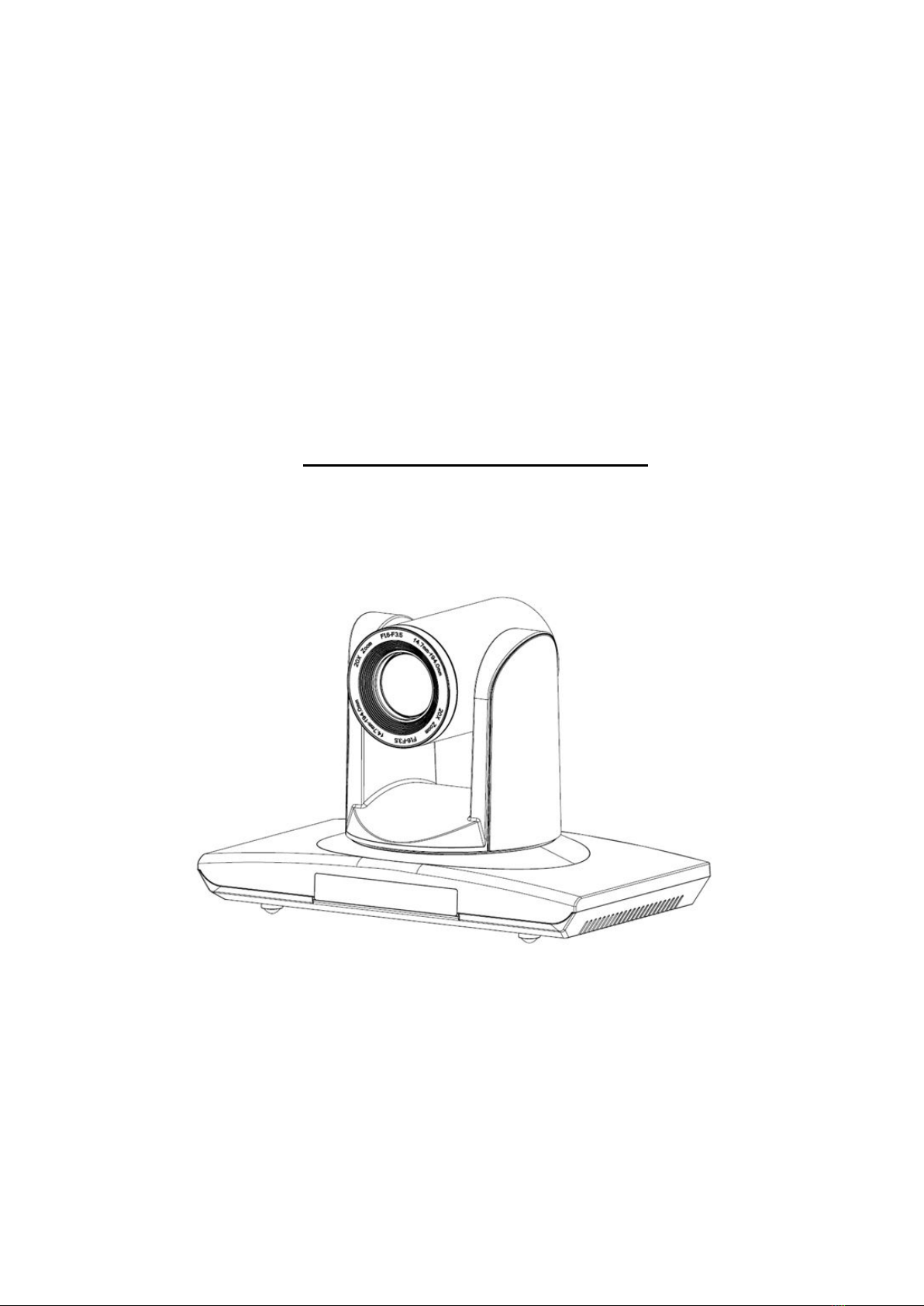
Camera Interface Explanation
1.Camera lens
2.Camera base
3.Power indicator light
4.Remote Controller Receiver light
5.Bottom dial Switch
6.Tripod screw hole
7.Installation Orientation Hole
8.Rotary Switch : video format optional
9.RS232 controller serial interface (input )
10.RS232 controller serial interface (output )
11.CVB interface (for selection)
12.HD-SDI interface
12.DVI-I interface(including YPbPr ,HDMIHD Digital Output and VGA interface) .
13.DC12V Input Power Supply Jack
14.Power Switch(red)
15.Power indicator light(red)
Dimension:

9
Remote Controller Explanation
Definition of IR controller
0、Standby key
After pressing the standby key, the camera
will step into standby mode.Press again,the
camera will open again.(Note: Standby mode
power consumption is about half of the normal
mode)
1、Number key
Setting or locating presets
2、* key
Key combination use
3、Set preset key:
Set preset:
Set preset key + 0-9 number key:
Clear preset key:
Clear preset key + 0-9 number key
or:#+#+#:clear all the presets
4、BLC control key
BLC ON:open black light compensation(only
work when exposure mode setting is Auto)
BLC OFF :close black light compensation
(Only available in the exposure mode
effective for Auto)
5、Focus control key
Focus+:focus length far from near
Focus-:focus length near from far
Auto focus:the camera focus mode is auto
Manual focus:the camera focus mode is manual
6、Camera address selection
Select the camera which want to be controlled
7、# key
8、pan/tilt control key
Press key :up

10
Press key :down
Press key :left
Press key:right
“HOME” key: Return to the middle position
9、Menu setting
Open or close the OSD menu
10、Zoom Control key
zoom+:lens near
zoom-:lens far
11.Camera IR remote control address selection
【*】+【#】+【F1】:Camera Address No.1
【*】+【#】+【F2】:Camera Address No. 2
【*】+【#】+【F3】:Camera Address No. 3
【*】+【#】+【F4】:Camera Address No. 4
Autres manuels pour UV830 Series
2
Table des matières
