M.I. P/N 004-2163 Rev. C 5
Power Input
The system has a universal power input, so it can accept 110V or 220V at 60Hz or 50Hz
(47Hz minimum, 63Hz maximum). The system includes two power cords: one with a
North American (NEMA) 5-15 plug and one with a European CEE (7)VII plug. If your
region requires a different plug type, contact your distributor or see the Technical Support
section for a source of power cords. See the Technical Specifications section for more
specific information about the power requirements.
CAUTION – Reliable earth connection is required. This device is designed to be
connected to protective earth through the power cord and the wall outlet. If your wall
outlets do not have a grounding conductor, please contact an electrician for installation. Do
not use groundless adapters.
The power switch is located on the back panel of the MPVS Ultra.
The green LED on the front panel will indicate whether the MPVS Ultra is turned on.
System Ground
For operator safety and signal noise reduction, an equipotential (earth ground) post is
located on the rear panel. This terminal can be used to ground the subject and any sensitive
equipment. Keep electrically noisy equipment such as lamps, heaters, and electrocautery
generators as far from the system as possible. See the Recommended Accessories section
for ordering information for equipotential cables specifically made for this type of terminal.
Data Acquisition
The system can be connected to any data acquisition system with sufficient voltage input
channels to accept the desired number of signals. Users with an ADInstruments PowerLab
system should refer to the ADInstruments PowerLab setup section for specific instructions.
For users with other data acquisition systems, packages of BNC-to-BNC cables are
available. See the Recommended Accessories section for ordering information.
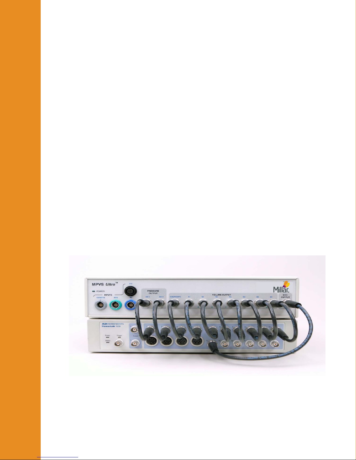
Connect each channel of the MPVS Ultra to the data acquisition system. Millar
recommends that the order of the channels be consistent with the order in which they are
arranged on the front panel of the MPVS Ultra. (Channels on the front panel are numbered
1 through 11.) A user may choose not to connect certain outputs, but consistency from one
study to the next is important to prevent problems in analyzing the data. Most users will
not use the Cuvette Output and Cuvette Temperature signals available on the rear panel.
(The Cuvette Temperature output can be used for a thermodilution measurement. See the
“Theory of Operation –Temperature Measurement” section for details.)
Pressure-Volume Cable
The P-V cable connects the catheter to the system. The cable is available in two different
lengths according to the users’ needs.
One end connects directly to the white low profile and gray circular connectors on the
catheter and the other end plugs into the color-coded (black) pressure-volume channel
receptacle on the front of the MPVS Ultra.
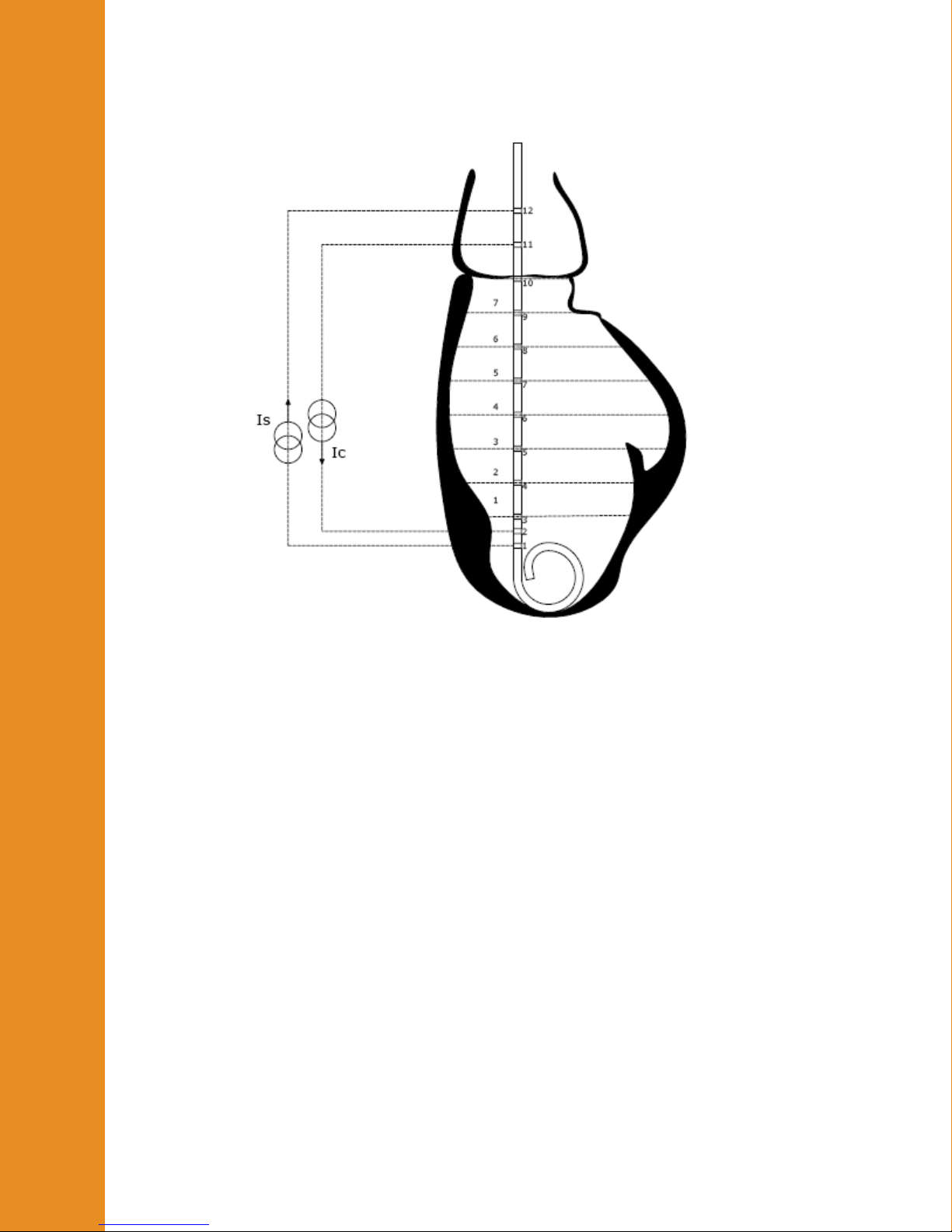
This cable carries the excitation signal from the MPVS Ultra to the catheter electrodes and
returns the pick-up signal from the sensing electrodes. This cable also carries the excitation
signal from the MPVS Ultra to the pressure sensor bridge as well as the pressure signal
back to the MPVS Ultra. When the system is used to record the internal ECG (IECG), the
signal is measured from the catheter through the P-V cable.
Gettin
Started
Gettin
Started