Milford Instruments BigFoot Manuel utilisateur

1
Milford Instruments Limited, Milford House, 120 High Street, South Milford, LS25 5AQ England
Tel 01977 683665, Fax 01977 681465 www.milinst.com
Milford Instruments Ltd
BigFoot
Contents:
Kit Contents page 2
Introduction page 3
Electronics Board page 4
Programming page 5
Fitting the Servos page 6
Ankle construction page 7
Foot construction page 8
Body board/Pace wires page 9
Leg Tendons page 10
Assembling the Toe switches page 11
PCB Mounting- Setup and run page 12
Fine tuning page 13
Schematic page 15

2
Milford Instruments Limited, Milford House, 120 High Street, South Milford, LS25 5AQ England
Tel 01977 683665, Fax 01977 681465 www.milinst.com
Kit Contents
Printed Circuit Board 1
“Toe” circuit board 2
4 x AA Battery Holder 1
Set Pre-cut body parts 1
150mm 48thou dia piano wire 3
150mm 22thou dia piano wire 2
25x1mm dia brass tube 2
20x2mm dia brass tube 2
300 mmx1mm dia brass wire 2
50mmx2.5mm cable sleeving 1
500mm twin wire 1
2 way plug socket 2
Cable pins 4
2-way header pins 2
Foam Pads 2
Manual 1
Diskette 1
Additional Items:
PBASIC 1.4 Chip 1
93LC56 Chip 1
Servo Motor 2

3
Milford Instruments Limited, Milford House, 120 High Street, South Milford, LS25 5AQ England
Tel 01977 683665, Fax 01977 681465 www.milinst.com
Introduction
BigFoot is a fully walking humanoid robot. It achieves this by using only two servo
motors controlled by the Parallax BASIC Stamp microcontroller.
One servo operates to roll the centre of gravity from one foot to the other whilst the
second servo controls the pace of the legs.
BigFoot is fitted with twin LED “eyes” and “Toe” switches that make him back-up
when he contacts anything.
If fitted with good quality NiCad type batteries, BigFoot should continue to wander
for about 1 hour.
If you bought BigFoot in the UK or directly from Milford Instruments, then the
operating programme will have been pre-loaded into the EEPROM chip and will
require no further programming.
If you bought BigFoot in the USA or if you wish to experiment by changing the
programme, you may need to make a programming cable (as shown on page 5)
and to load the programme from diskette.
Once you have checked the kit items against the contents list, we suggest you work
in the order presented in this manual.
In addition to the assembly sketches shown in this manual you may also wish to
view actual construction stage photographs in the BigFoot section of our web site-
www.milinst.com

4
Milford Instruments Limited, Milford House, 120 High Street, South Milford, LS25 5AQ England
Tel 01977 683665, Fax 01977 681465 www.milinst.com
Electronics Board
If not already fitted, fit the 18-pin chip marked PBASIC1.4 and the 8-pin chip
marked 93LC56. Ensure the depression on one end of the chip corresponds to the
diagram below.
Connect the two servos to the 3-pin headers on the board- ensure they are fitted
the correct way round.
With the ON-OFF switch set to OFF, insert 4xAA Nicad batteries into the holder
and connect to the circuit board using the flying lead provided.
Switch the board ON- the servos should move to their center position for 2
seconds and then move in an oscillating manner and the LEDs toggle on and off. If
not- immediately switch OFF and check the installation of the two chips and
battery.
The electronics board is now ready and tested.
If you bought the kit in the USA then you may need to load the programme -
please do this as indicated on page 5 before proceeding further.
Note on BatteriesNote on Batteries
Servo motors have a high current requirement- for this reason it is important thatServo motors have a high current requirement- for this reason it is important that
onlyonly NiCadNiCad oror NiMH (NiMH (Nickle Metal Hydride) batteries are used.Nickle Metal Hydride) batteries are used.
Standard Zinc, Alkaline or Alkaline/Manganese batteries will not work and mayStandard Zinc, Alkaline or Alkaline/Manganese batteries will not work and may
cause loss of the embedded programme.cause loss of the embedded programme.

5
Milford Instruments Limited, Milford House, 120 High Street, South Milford, LS25 5AQ England
Tel 01977 683665, Fax 01977 681465 www.milinst.com
Programming
This section is only applicable if you bought the kit in the USA or wish to modify the
programme
If you weren’t supplied with a programming cable, make up a suitable cable as
shown in figure 2.
Connect the programming cable to the PC printer port and to the 3-pin header on
the electronics board.
Ensure your PC is in MSDOS mode (if you are running Windows ’95 etc then you
will have to instruct the machine to re-boot in MSDOS mode).
Insert the diskette in drive A
Type AA:: press Enter
Type stamptamp press Enter
Press ALT- LALT- L this will display the available .bas files
Scroll using the Up/Down keys until bigfoot.basbigfoot.bas is highlighted press Enter
The bigfoot.basbigfoot.bas programme should now be showing on the screen
Switch the electronics board ONON
Press ALT- RALT- R
The loading window should now appear and a white bar shows the programming
status.
If all is well the programme will indicate programming success and the LEDs on the
electronics board will start to flash. If programming has not been successful a
warning message will be shown- if this occurs check that the 3-pin header is the
correct way round, that the cable connections are correct and that the electronics
board switch is set to ON.
If you wish to experiment with the programme, the programme may be altered
using straightforward text when displayed on the screen. Any new version may be
saved by pressing ALT S- give the file a name other than bigfoot.bas otherwise your
original file will be overwritten!
Now return to complete the testing of the electronics board.
Programming Cable Details- Figure 2
D-25 PlugD-25 Plug
Pin 25 GND
Pin 11 BUSY
Pin 2 DO
3-Way header and socket
PC
PC

6
Milford Instruments Limited, Milford House, 120 High Street, South Milford, LS25 5AQ England
Tel 01977 683665, Fax 01977 681465 www.milinst.com
Fitting the Servos
Please take care with the following steps- it is important that the servos are squarePlease take care with the following steps- it is important that the servos are square
within the side cheeks and that the side cheeks are parallel to one anotherwithin the side cheeks and that the side cheeks are parallel to one another
Using a glue gun or double sided tape, stick one servo to the side cheek as shown
in figure 3.
Make sure the FRONT edge of the servo is parallel to the edge of the cheek
otherwise it will affect the way BigFoot walks.
Figure 3
Front of servo parallel to the front edge of side cheek and against top edge. Fit with circular horn
Now fit the second servo- this time make sure the REAR edge of the mounting
flange is parallel to the edge of the side cheek.
Figure 4

7
Milford Instruments Limited, Milford House, 120 High Street, South Milford, LS25 5AQ England
Tel 01977 683665, Fax 01977 681465 www.milinst.com
Rear edge of servo flange parallel to edge of side cheek and positioned mid-way. Fit with 2-lever
horn.
Fit the second side cheek to the servos. Make sure the edges of both cheeks are
parallel and aligned with one another.
Ankle Construction
Take a length of 1mm diameter brass wire and bend to the following shape:
Insert the wire into the ankle piece and fix in place with hot-melt glue or similar.
Fix, using hot-melt glue, an 85mm long piece of brass wire along the bottom
edge.
Repeat for the other ankle piece noting that they are handed
15mm 53mm
Stage 1
30mm 23mm
Stage 2
51mm
Bend upwards here
Figure 5

8
Milford Instruments Limited, Milford House, 120 High Street, South Milford, LS25 5AQ England
Tel 01977 683665, Fax 01977 681465 www.milinst.com
Foot Construction
Build the right foot as shown below
Fit the leg sections to the foot. Use short lengths of sleeving pushed over the ends
of the brass wire to secure in place.
Build the left foot and leg in a similar manner (note again that it will be the mirror
image of the right foot).
Secure with short piece
of sleeving
Figure 9
Ensure ankle support pieces are
perpendicular to the edge of the
foot and aligned with the edge
15mm
Hole for leg tendon
Figure 8

9
Milford Instruments Limited, Milford House, 120 High Street, South Milford, LS25 5AQ England
Tel 01977 683665, Fax 01977 681465 www.milinst.com
Body Board
Fix the servo block to the top board with hot-melt as shown- it must be
perpendicular to the top board.
Cut two 50mm lengths of brass wire. Push these through the holes in the top of the
legs and side cheeks to secure the legs to the body. Slip pieces of sleeving over the
ends to keep in place.
Bend the Left hand “Pace” wires as shown below and fit to the Left leg and “pace”
servo.
Stage 1 Stage 2 (Plan view)
Make and fit a similar (but right-handed) piece for the right leg. Secure in place
with sleeving.
30mm
10mm
10mm
18mm
Bend here
Figure 11
Figure 12
51mm
51mm
15mm
Figure 10
10
Milford Instruments Limited, Milford House, 120 High Street, South Milford, LS25 5AQ England
Tel 01977 683665, Fax 01977 681465 www.milinst.com
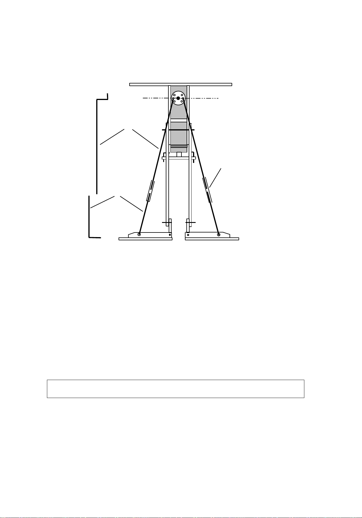
Leg Tendons
Support the legs and top board with the legs vertical and with the feet together and
horizontal.
Choose two diametrically opposite holes in the circular “roll” servo horn and
ensure these are level above the feet.
Cut and bend the lengths of piano wire as shown. Epoxy (or solder) the brass tube
to the lower wires making sure the end is approximately ½ way up the tube.
Thread the upper wires into the holes on the servo horn- make sure they are level.
Slip the lower wire tube onto the end and insert the lower end into the foot hole.
Ensure everything is vertical and symmetrical as shown above before completingEnsure everything is vertical and symmetrical as shown above before completing
the joint with either epoxy or solder.the joint with either epoxy or solder.
Imaginary line through chosen holes is parallel
with top piece
37mm
135mm
5mm
10mm
Top wire
15mm
Lower wire
25mm
brass tube
Figure 13
Table des matières
Manuels Robotique populaires d'autres marques

STEMCenter USA
STEMCenter USA Pi-Bot v2.00 Manuel utilisateur

SunFounder
SunFounder PiDog Manuel utilisateur

Universal Robots
Universal Robots UR5 Manuel utilisateur

Universal Robots
Universal Robots E Series Manuel utilisateur

YASKAWA
YASKAWA MOTOMAN-MPL80 II Manuel utilisateur

EFORT
EFORT ECR5 Manuel d'instructions


